24 UK
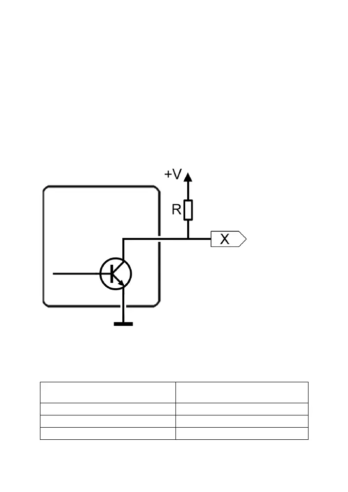
Tamper
These connector clamps are normally connected to the tamper zone or
tamper line of an alarm control panel. When the housing is opened, the NC
contact of the device is also opened, interrupting the tamper line. This
triggers a tamper alarm on the alarm control panel.
Outputs (OP1 to OP4)
Four negative switching transistor outputs are present.
Each output can switch a maximum of 100 mA, that is, the power
consumption of the connected circuit of the external device should not be
higher than 100 mA.
(maximum switching current of 100 mA)
Example
In the example wiring diagram, “R” represents an external device, such as
an LED or relay.
If you have selected the “Outputs Output Polarity = Negative” menu item: