Reference the following notes when diagnosing electrical
problems.
• The ignition system timing is non-adjustable. The
specifications in Chapter 1 are intended for reference only.
• Refer to wiring diagram for stator and electrical component
resistance specifications.
• When measuring resistance of a component that has a low
resistance value (under 10 Ohms), remember to subtract meter
lead resistance from the reading.
Connect the leads together and record the resistance.
The resistance of the component is equal to tested value minus
the lead resistance.
• Become familiar with the operation of the meter. Be sure
leads are in the proper jack for the test being performed (i.e.
10A jack for current readings). Refer to the owner’s manual
included with the meter for more information.
• Voltage, amperage, and resistance values included in this
manual are obtained with a Fluke™ 77 Digital Multimeter.
This meter is acceptable for use when diagnosing electrical
problems. Readings obtained with other meters may differ.
• Pay attention to the prefix on the multimeter reading (K, M,
etc.) and the position of the decimal point.
• For resistance readings, isolate the component to be tested.
Disconnect it from the wiring harness or power supply.
• The letter of wires color show as following:
B Black
R Red
Y Yellow
W White
L Blue
P Pink
BR Brow
G Green
O Orange
DB Deep blue
DG Deep green
B/W Black/ White
B/R Black/ Red
Y/W Yellow/ White
Y/L Yellow/ Blue
Y/R Yellow/ Red
G/R Green/ Red
G/Y Green/ Red
W/R White/ Red
W/L White/ Blue
L/R Blue/ Red
L/W Blue/ White
L/B Blue / Black
R/W Red/ White
BR/W Brown/ White
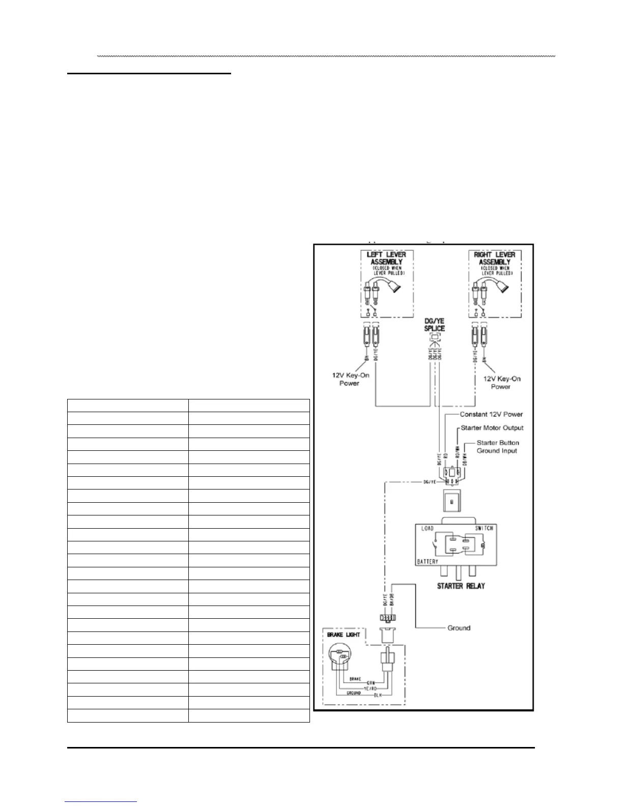
Brake Lever Switches
Each brake lever utilizes an electrical brake switch that sends
voltage to activate the starter relay and brake light.
1. Locate the brake switches on each of the brake levers.
2. Disconnect wire harness from brake switch and connect an
ohmmeter across the two switch wires.
The reading should be infinite (•).
3. Apply brake the brake lever(s) and check for continuity
between switch contacts. Replace switch if there is no
continuity or if the resistance is greater than .5 ohms when the
brake is applied with slight pressure.
8.2
 Loading...