FUEL SYSTEM
Air / Fuel Mixture Ratio
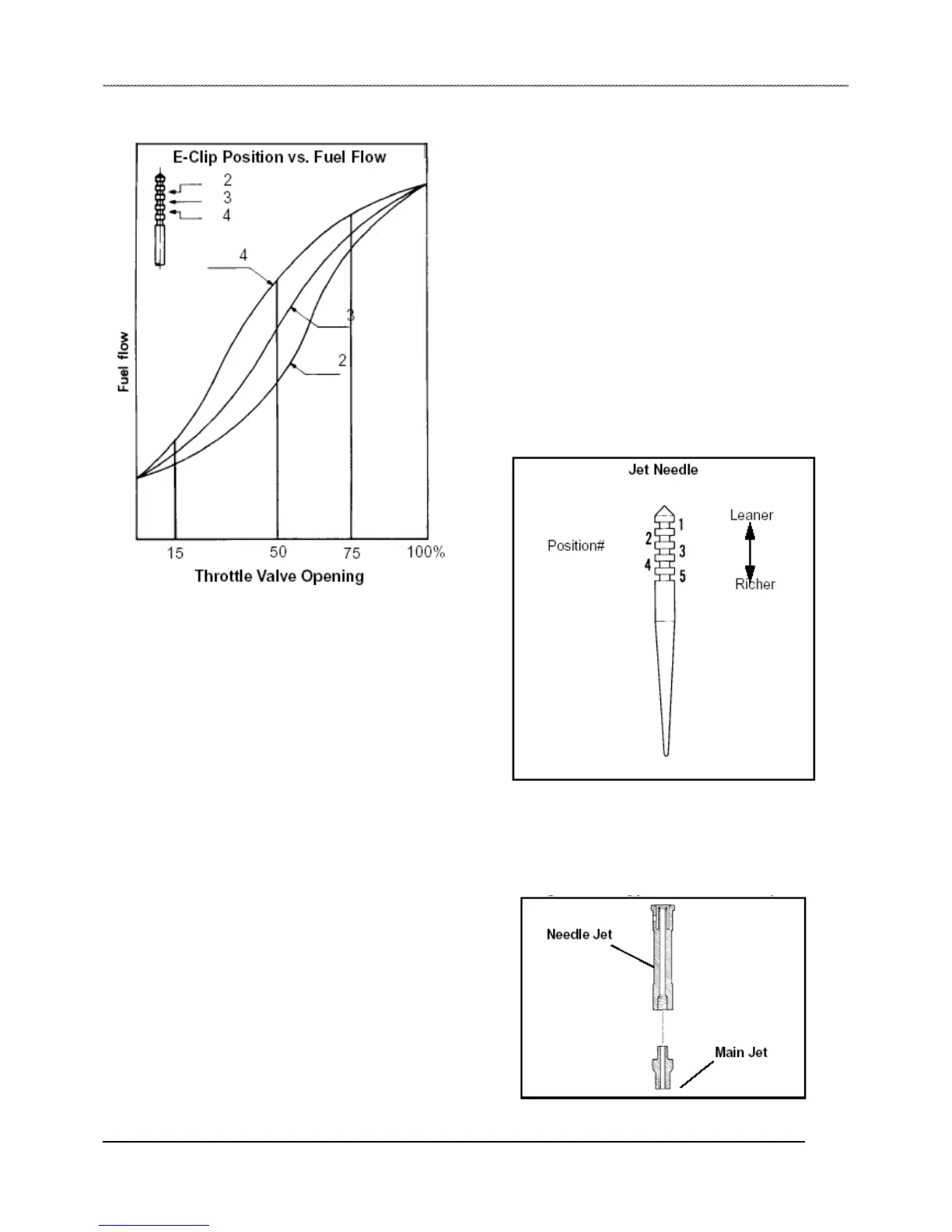
Jet Needle
The jet needle has five adjustment grooves cut into the upper
portion, and is tapered from approximately the middle of the
needle to the lower end. The top is fixed to the center of the
throttle valve by the needle clip, and the tapered end extends
into the needle jet. Fuel flows through the space between the
needle jet and jet needle. This space does not vary until the
throttle reaches the 1/4 open point. At that time the tapered
portion of the needle begins to move out of the jet, affecting
fuel flow as the opening enlarges. If the needle clip is changed
from the standard position to a lower groove, the needle taper
starts coming out of the jet sooner, resulting in a richer
mixture. Moving the clip higher produces a leaner mixture. If
the taper is worn due to vibration, fuel flow may be
significantly affected.
A carburetor with a slide type throttle valve is also called a
variable venturi type carburetor. In this type of carburetor, the
needle jet and jet needle serve to control proper air/fuel
mixture ratio at the medium throttle valve opening (between
1/4 and 3/4 opening).
Having the proper needle jet and jet needle has a major impact
on engine performance at partial load. The jet needle tapers off
at one end and the clearance between the jet needle and the
needle jet increases as the throttle valve opening gets wider.
The air/fuel mixture ratio is controlled by the height of the “E”
clip inserted into one of the five slots provided in the head of
the jet needle. The previous chart shows the variation of fuel
flow based on the height of the “E” clip.
Needle Jet
The needle jet works in conjunction with the jet needle to
regulate fuel flow rate. An air bleed opening in the side of the
needle jet brings in air measured by the air jet. This air initiates
 Loading...