ELECTRICAL
Main Fuse / Fuse Holder Location
A 7 Amp fuse protects the main electrical system on all
models. See illustrations for fuse locations.
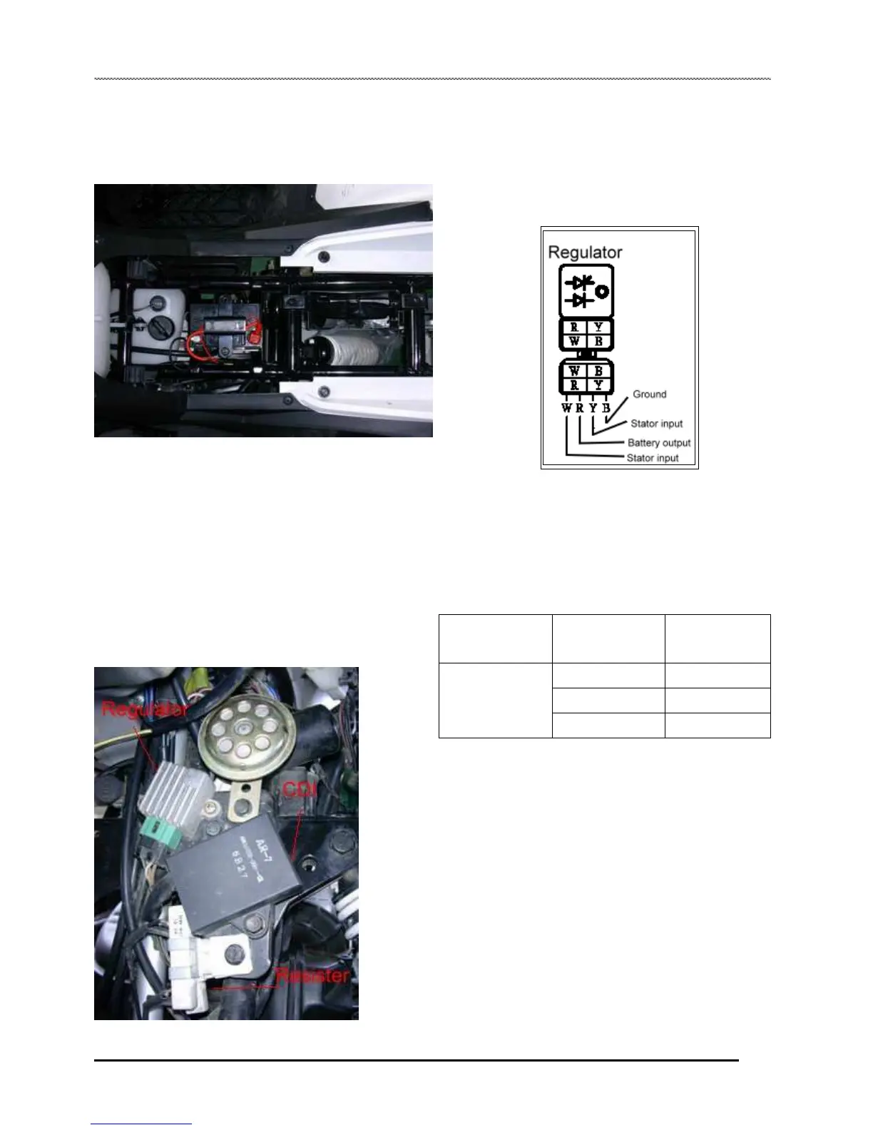
2. If a problem exists with the charging system, test the
components around the regulator/rectifier to isolate the
component. If the stator is supplying sufficient AC current and
there is no DC current leaving the regulator/rectifier, replace
the component.
NOTE: Use only the recommended fuse capacity, as
use of a higher amperage fuse to correct blown-fuse
situations could lead to electrical component
damage.
Stator / Alternator Tests
Two tests can be performed using a multimeter to determine
the condition of the stator (alternator).
TEST 1: Measure resistance value of each stator leg.
1. Measure the resistance value of the stator legs. Use the
following chart as a reference when testing.
Voltage Regulator / Rectifier
1. The voltage regulator / rectifier is located under the
headlight of front cab on all model.
Ohm Test Connect
Meter Leads To:
ΩReading
Battery Charge Coil
Black to Ground
0.1Ω±20%
Black to Yellow
0.5Ω±20%
Black to White
0.6Ω±20%
TEST 2: Measure AC voltage output of each stator leg. Test at
cranking rpm with a voltmeter set to read AC volts.
2. Turn over the engine with the starter motor.
3. First measure from the red wire (R) to engine ground.
Compare readings to specifications.
4. Next measure from the yellow wire (YE) to engine ground.
Compare readings to specifications.
8.11
 Loading...