ELECTRICAL
RPM Ignition Limiter Functions
NOTE: The CDI box reads the RPM signal from the
stator. The CDI box acts as a limiter by retarding the
ignition timing if RPM reaches the specified limit. In
reverse gear, the CDI box retards ignition timing and
limits RPM once it receives a ground path from the
transmission switch blue (L) wire indicating the ATV
is in reverse.
CDI WIRES
PLUG COLOR DECCRIPTION
3-WIRE
B/W KEY SWITCH “OFF” SIGNAL INPUT.
R/W FLYWHEEL IGNITION ANGLE SIGNAL
INPUT.
B/R STATOR IGNITION VOLTAGE INPUT.
6-WIRE
BR DC VOLTAGE INPUT.
B GROUND
GRAY/ Y REVERSE SIGNAL
GRAY/ L NEUTRAL
G/Y BRAKE LIGHT SIGNAL
W/L IGNITION COIL DC INPUT.
CDI Output Test
Using Peak Reading Adaptor
Re-connect all wires to the CDI box. Disconnect the
white/blue CDI output wire from ignition coil primary
terminal. Install the Peak Reading Adaptor to your meter and
connect one meter lead to engine ground and the other to the
white/blue CDI Output wire at the ignition coil. Set meter to
read DC Volts. Crank engine and verify CDI output to the
ignition coil. When finished, reconnect CDI output wire to
ignition coil.
Test Description Resistance
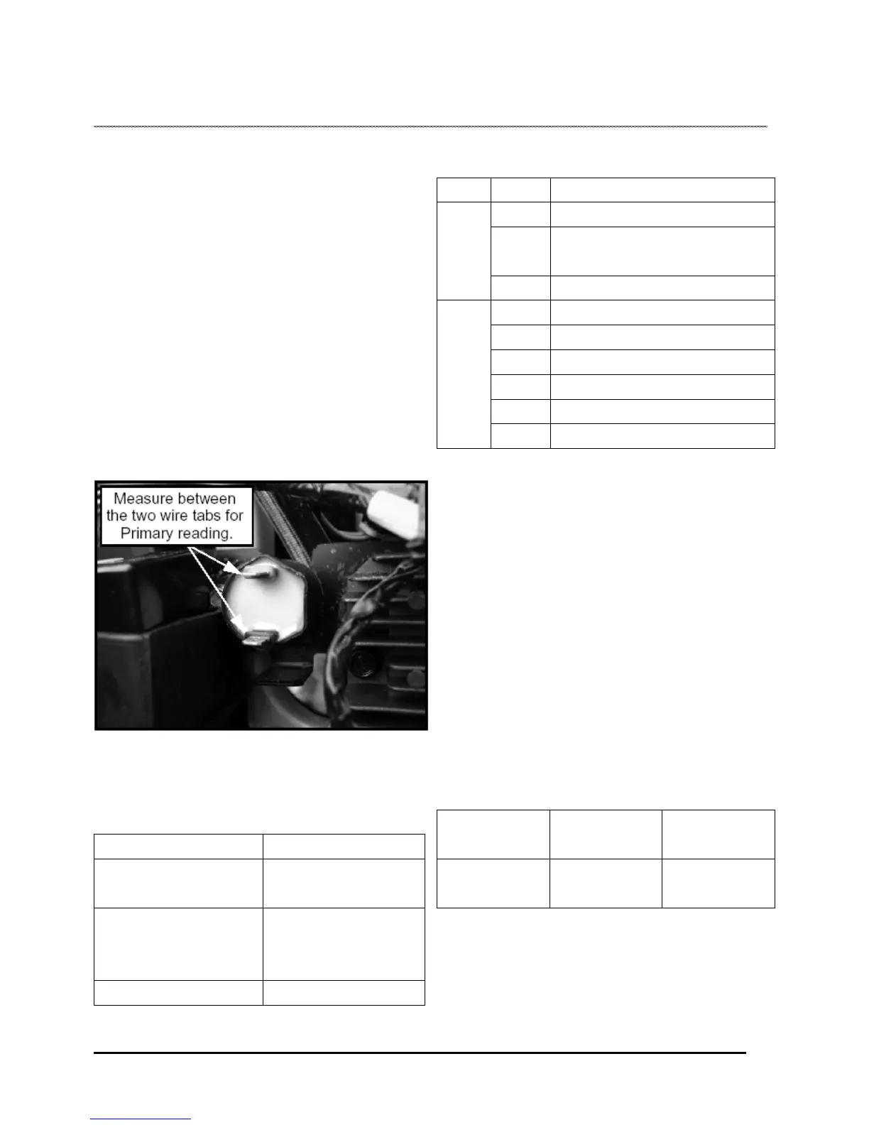
Ignition Coil Primary Winding
0.2 Ω ± 20%
Ignition Coil Secondary
Winding (With Cap Installed)
(Without Cap Installed)
8 K Ω ± 20%
3 K Ω ± 20%
Spark Plug Resistor Cap
5 K Ω
Out put test Connect meter lead
to:
Reading
CDI output W/B to
Engine Ground
180DC Volts ±
20%
8.9
 Loading...