AEQ FORUM
Digital audio mixer for broadcast applications
37
• “SETUP”: which displays and allows you to change the IP configuration associated with
the two Ethernet ports available on the rear panel of the equipment (“LAN” and
“ETHERNET”: see section 2.2.2.2 of this manual) in the form of IP address (IP1 or IP2),
subnet mask (MASK) and gateway (GWAY). Only level 3 users can modify these
parameters (the “SETUP” key is shown to other users but is not active).
• “SELECT”: advanced configuration of audio inputs/outputs, internal routing and
processes.
3.4.1. “INFO“ menu.
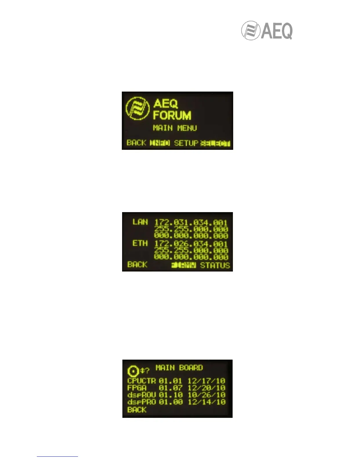
This is a menu specifically for technical maintenance. The “INFO” menu lets you display the IP
configuration associated with the two Ethernet ports available on the rear panel of the
equipment (“LAN” and “ETHERNET”: IP address, subnet mask and gateway are shown), the
firmware versions installed in the several console operating modules and the routing and
process DSPs percentage of use.
The three options visible on the last line of the display are associated with three of the four
contextual keys below, from left to right:
• “BACK”: pressing this key allows you to return to the previous menu screen.
• “FIRMW”: in successive screens, which are accessed by turning any of the associated
encoders, you can display the firmware versions installed in the different modules that
make up the console: the 4 modules that make up the main board of the console (CPU,
FPGA, Routing DSP and Process DPS) are shown as “MAIN BOARD” and the MSC
module (control and monitoring section) and the FSC modules (4 faders modules or
FRCH) are shown as “CONTROL SURFACES”.
Each line is identified by the specific module and its reference, as well as the version
and the date of the currently installed specific firmware.