AEQ FORUM
Digital audio mixer for broadcast applications
46
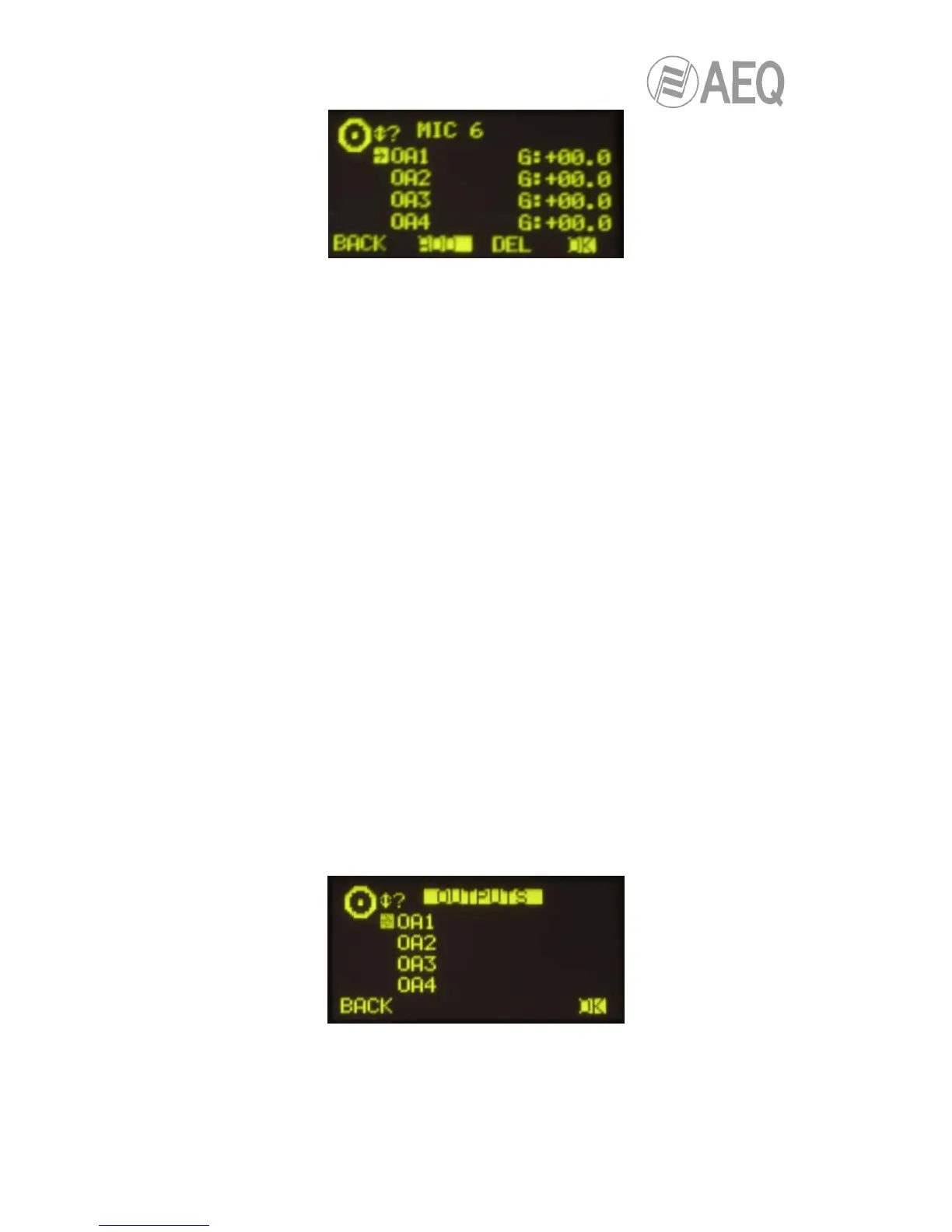
The operation of the contextual keys, from left to right, is as follows:
• “BACK”: pressing this key allows you to return to the previous menu screen (the
changes you may have made are saved).
• “ADD”: enables you to create the cross-point toward the output signal or bus that is
highlighted at that moment.
• “DEL”: enables you to delete the cross-point toward the output signal or bus that is
highlighted at that moment.
• “OK”: pressing this key allows you to return to the previous menu screen (the changes
you may have made are saved).
The routing toward the “Program”, “Audition”, “Aux1” and “Aux2” internal buses works in a
different way depending on the assignment of the selected input to a fader or not:
- when the input is assigned to a fader and, in the previous list, you select “Program” bus
(for instance), when you press the “ADD” key the routing key (“PROGRAM” in this case)
of the channel is activated (the associated LED is lighted). In the display, the cross-
point toward that bus appears for a moment and then dissappear. The “DEL” key has
no associated function in that case (you must press the “PROGRAM” channel key to
deactive that routing). If now you press the “ON” key of the channel, the cross-point
appears now in the display (if you rise the fader, the “ON AIR” indicator will light); in that
case, the “DEL” key allows you to deactive the routing toward that bus (the cross-point
disappear and the “PROGRAM” channel key turns off).
- when the input is not assigned to a fader and, in the previous list, you select “Program”
bus (for instance), pressing the “ADD” key is equivalent to set that input “ON AIR” (the
cross-point appears and, if gain is not configured at its minimum value, signal is sent to
that bus). The “DEL” key allows you to deactive that routing (the cross-point
disappears).
3.4.3.2. “OUTPUT“ menu.
This menu shows a list of all the audio output logical signals defined in the system from the
configuration software, followed by the internal summing buses (“Program”, “Audition”, “Aux1”
and “Aux2”), the monitoring buses (“Cue”, “Studio” and “Control”) and finally the MPX buses.
For more information, see section “4. CONFIGURATION SOFTWARE” in this manual.
You can access a more complete description of each one of the output audio channels by
turning any of the 3 associated encoders and pressing then the “OK” contextual key or any of
these encoders. The information showed on this screen, from top to bottom and left to right, is: