AEQ FORUM
Digital audio mixer for broadcast applications
62
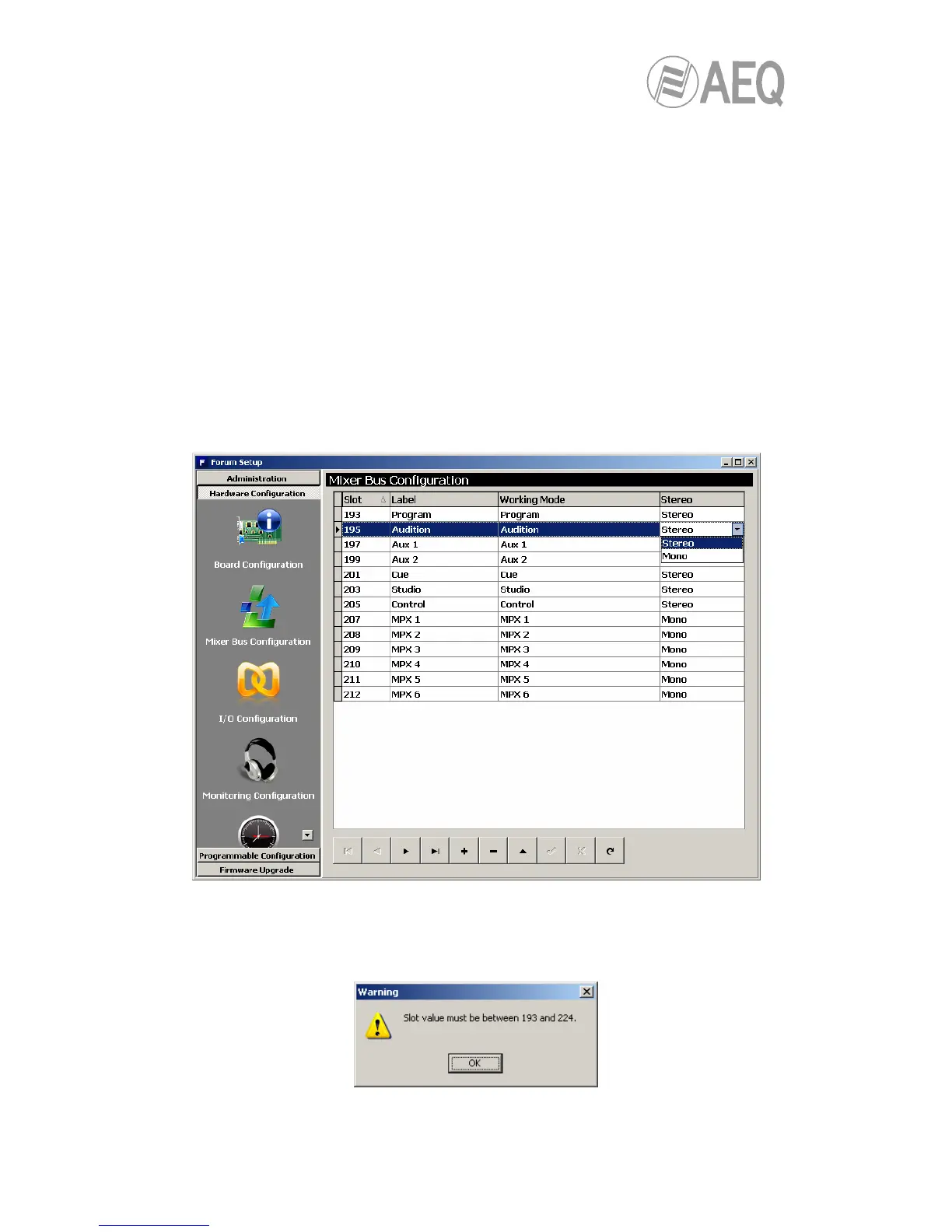
• “Control“: output bus toward control monitors and headphones, stereo and with
working mode defined as “Control”.
• “MPX 1“: mono and with working mode defined as “MPX 1”.
• “MPX 2“: mono and with working mode defined as “MPX 2”.
• “MPX 3“: mono and with working mode defined as “MPX 3”.
• “MPX 4“: mono and with working mode defined as “MPX 4”.
• “MPX 5“: mono and with working mode defined as “MPX 5”.
• “MPX 6“: mono and with working mode defined as “MPX 6”.
You can edit the "Label" for each mixer bus. If a mixer bus in factory configured as stereo is
reconfigured to mono, the liberated channel will pop up on the configuration screen as available.
The opposite would happen if you change the settings for an initially mono bus, “MPX 1” for
instance: when you reconfigure it for stereo operation, the next bus line, “MPX 2” in this case,
will disappear from the available buses on the configuration screen since this bus will be added
to “MPX 1”.
You can create up to 32 mono or 16 stereo mixer buses, including the 7 predefined stereo
buses and the 6 MPX mono buses as described above. The MPX buses can be expanded to up
to 8. The remainder of mixing buses can be defined as “Internal”.
The mixer bus configuration table has the following fields:
• “Slot”: indicates the internal position of this signal in the digital audio bus of the mixer.
The 32 available slots are numbered between 193 and 224 both inclusive. An error
message will appear when you try to define a bus above those 32 availble slots:
 Loading...