44
43434343
A B
HL2
...
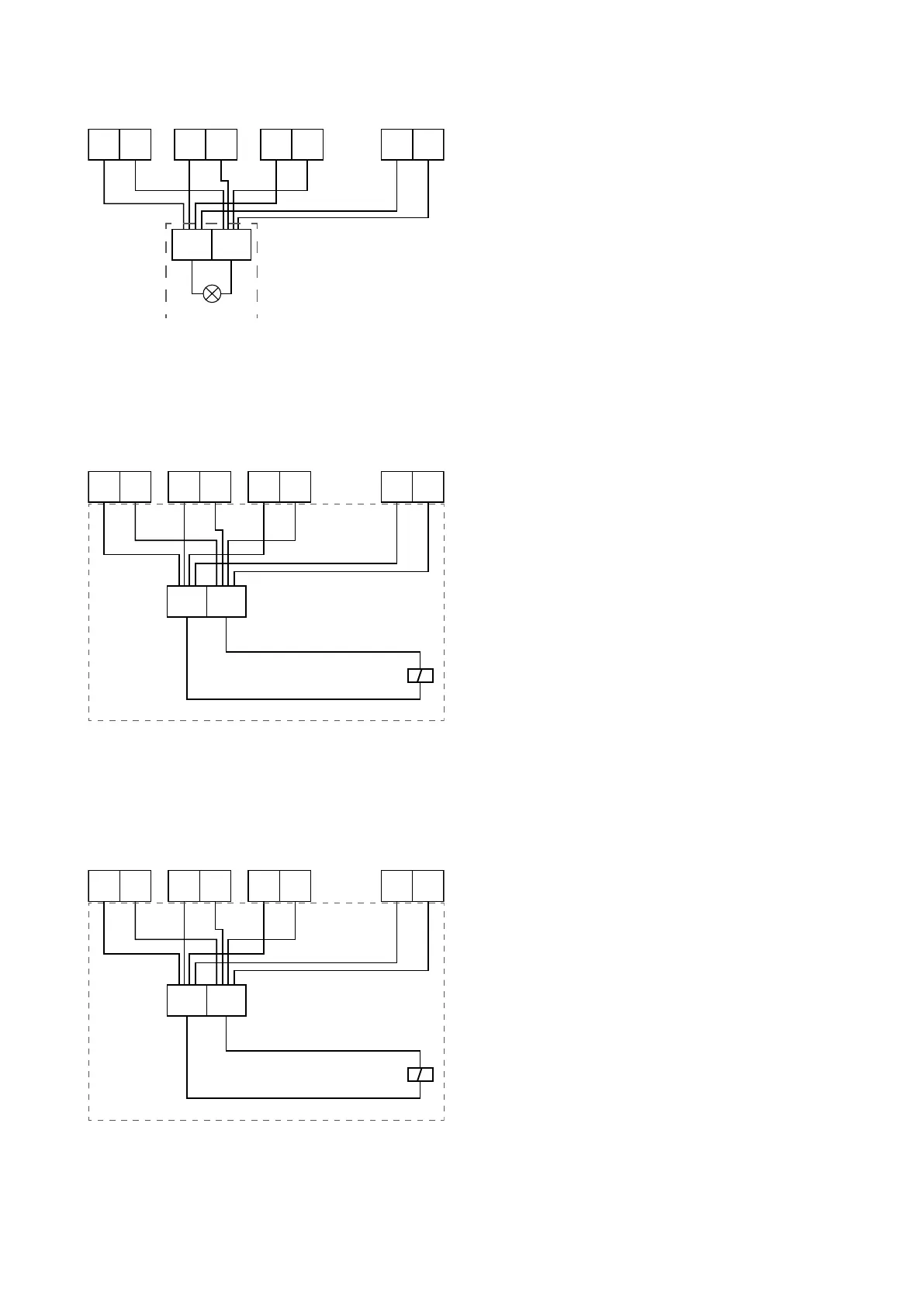
Unit 16Unit 3Unit 2Unit 1
When it is necessary to display the errors of several modular
units, terminals 3 and 4 of each module must be connected in
parallel to the outputs A and B of the alarm lamp installed (HL2).
KEY:
- - - - - - : not supplied
E F
65656565 ...
KM1
A1
A2
L1 N1
Unit 16Unit 3Unit 2Unit 1
G H
1211121112111211 ...
KM3
A1
A2
L1 N1
Unit 16Unit 3Unit 2Unit 1
When several modular units directly control one or more water
pumps, the relative terminals (5 and 6 for KM1 while 6 and 7 for
KM2) present on the terminal board of the board on each unit
must be connected to the respective terminals (E and F in the
example to the side), connected to the water pump contactor.
When several modular units directly control one or two auxiliary
electric heaters, the relative terminals (11 and 12 for KM3 while
13 and 14 for KM4) present on the terminal board of the board on
each unit must be connected to the respective terminals (G and
H in the example on the side), connected to the contactor of the
auxiliary electric resistance.