49
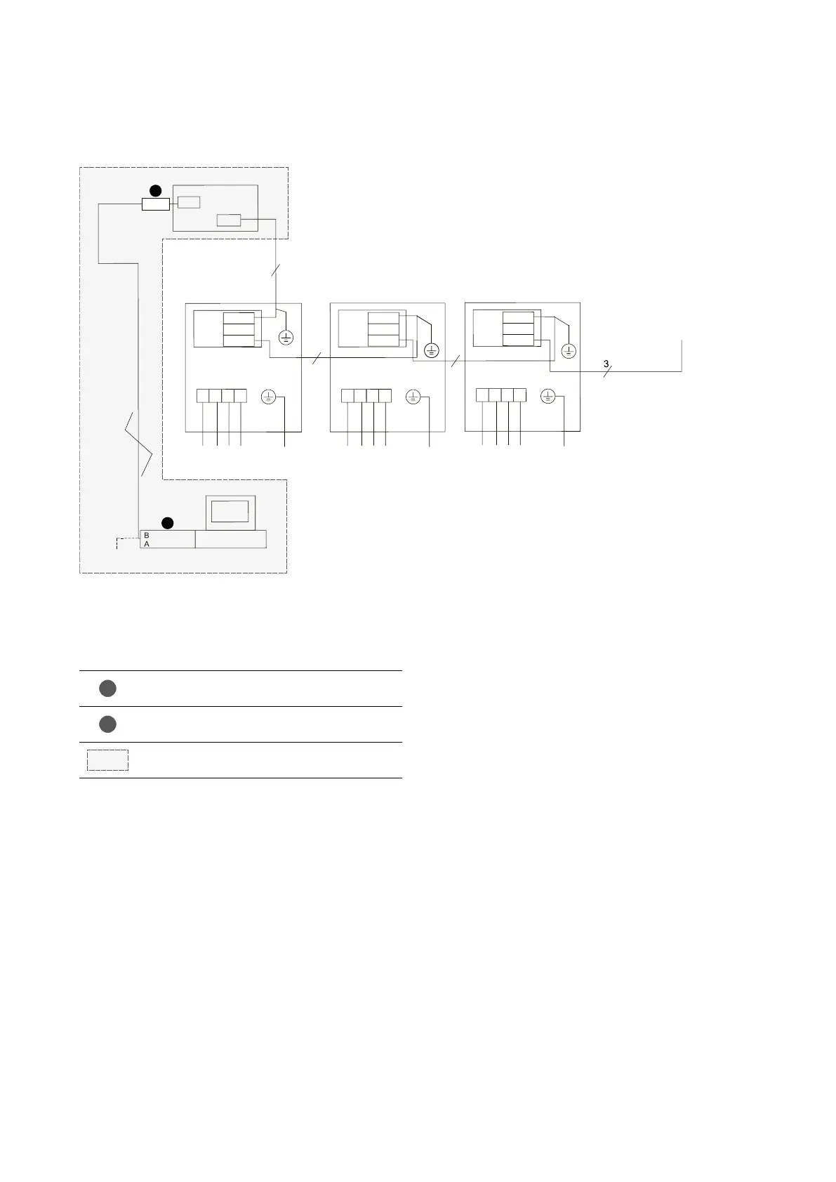
SERIAL CONNECTION BETWEEN WIRED
CONTROL PANEL AND MODULAR UNITS
NOTES
• Clamps CN33 and CN25 of each module are connected to each
other via a 3 wire, 4 pin shielded communication cable, the
grounding of which is connected to the terminal near the main
board.
• Clamp CN4 on the board of the wired control panel is connected
to clamp CN25 found on the main board of any unit via a 4-wire
shielded communication cable, the grounding wire of which
will be connected to the terminal near the main board.
• The electrical lines must be connected to L1, L2, L3 and N
which are found in terminal board XT1.
• The units may be integrated in BMS system by using the
ModBus protocol. (To view the list of variables refer to the
specific documentation found on our website www.aermec.
com)
* NOTE
A ModBus repeater must be used for RS485 serial connection
with supervision system when more than 30 control panels
are connected or when the communication line is longer than
800m.
1
2
BMS
CN2
CN4
4
CN33
AP1AP1AP1
CN15
CN25
XT1
NL3L2L1
PE
3
3
PE380
~
415V 50HZ 3N
CN33
CN15
CN25
CN33
CN15
CN25
XT1
NL3L2L1
PE
PE380
~
415V 50HZ 3N
XT1
NL3L2L1
PE
PE380
~
415V 50HZ 3N
IC-2P
PC for remote
monitoring
RS232/485
converter
Communication line
TCP
To the next unit ...
last unit (max. 16)
PC for remote
monitoring
RS232/485
converter
Communication line
AP1
HMG0350 electric boxHMG0600 electric boxHMG0600 electric box
To the next unit ...
last unit (max. 16)
Key
1
The connection can be made with the aid of
accessory IC-2P (not supplied)
2
Accessory USBDC (not supplied)
RS485 serial connection with supervision system *
Communication line
electric box electric box electric box
PC for remote
monitoring
converter