1290 Infinity II High-Speed Pumps User Manual 258
11 Hardware Information
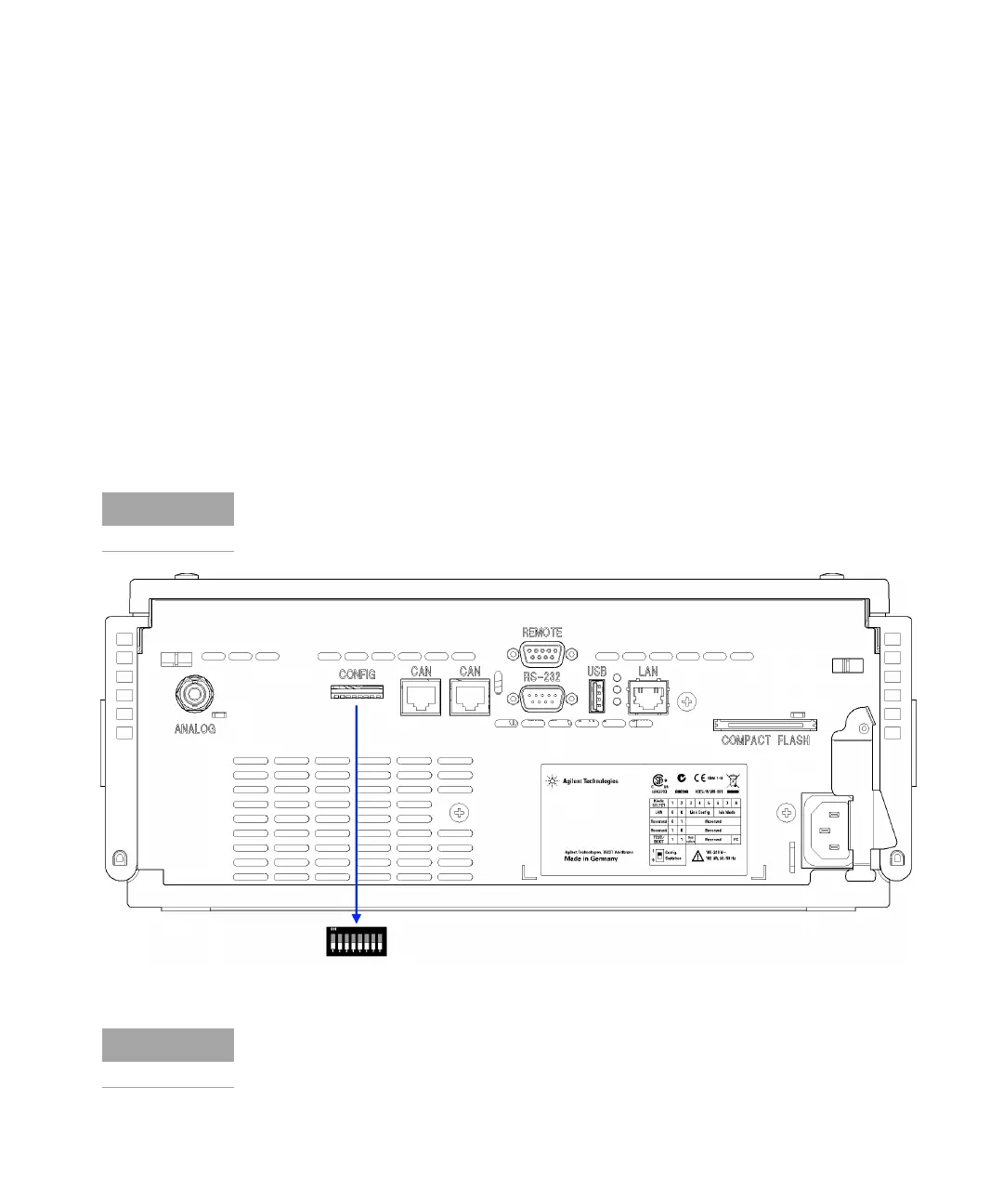
Setting the 8-bit Configuration Switch
Setting the 8-bit Configuration Switch
The 8-bit configuration switch is located at the rear of the module. Switch
settings provide configuration parameters for LAN, serial communication
protocol and instrument specific initialization procedures.
All modules with on-board LAN:
• Default is ALL switches DOWN (best settings).
• 19200 baud, 8 data bit / 1 stop bit with no parity for RS-232
• For specific LAN modes switches 3-8 must be set as required.
• For boot/test modes switches 1+2 must be UP plus required mode.
Figure 25 Location of Configuration Switch (example shows a G4212A DAD)
For normal operation use the default (best) settings.
To perform any LAN configuration, SW1 and SW2 must be set to OFF. For details
on the LAN settings/configuration refer to chapter LAN Configuration.

 Loading...


