Chapter 5 Straightness Measurements
Mounting and Aligning Optics for X-Axis or Y-Axis Measurements
Measurements Reference Guide 5-15
4 Lock the spindle in place, using, for example, a hose clamp and wedging
material. Then, remove the target from the interferometer.
5 Gently tap the interferometer assembly to ensure that its mounting is
rigid and free of vibration.
If you feel any vibration, tighten all connections in the mounting.
6 Set the laser head’s upper port to the large aperture.
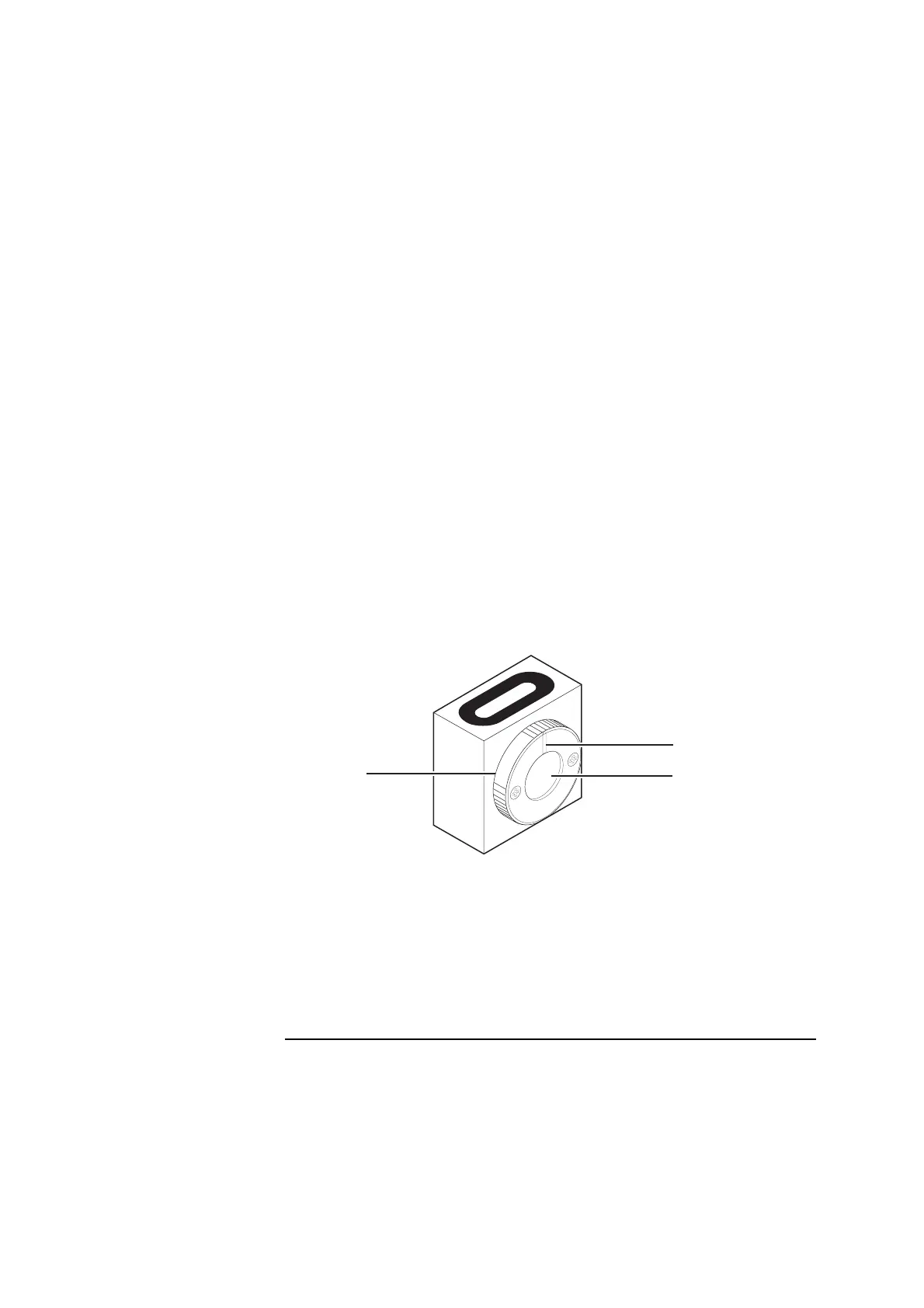
7 Rotate the interferometer’s bezel (Figure 5-9) so the scribe line is
perpendicular to the reflector’s slot.
Two beams should now be exiting the interferometer in a plane
perpendicular to the interferometer’s slot. The beams appear as dots on
the reflector. If you cannot see the beams, hold a piece of paper in front of
the reflector.
Figure 5-9. Interferometer bezel with scribe line
8 Move the reflector back and forth or side to side until the dots are aligned
vertically between the midpoint notches in the reflector’s slot
(Figure 5-10).
By doing this, you ensure that the beams strike the junction of the two
mirrors in the reflector.
1
Scribe line
2 Interferometer’s window
3 Interferometer’s bezel
L.R. STRAIGHTNESS
INTERFEROMETER
1A
00900
1
3
2
 Loading...


