Chapter 5 Straightness Measurements
Mounting and Aligning Optics for X-Axis or Y-Axis Measurements
5-16 Measurements Reference Guide
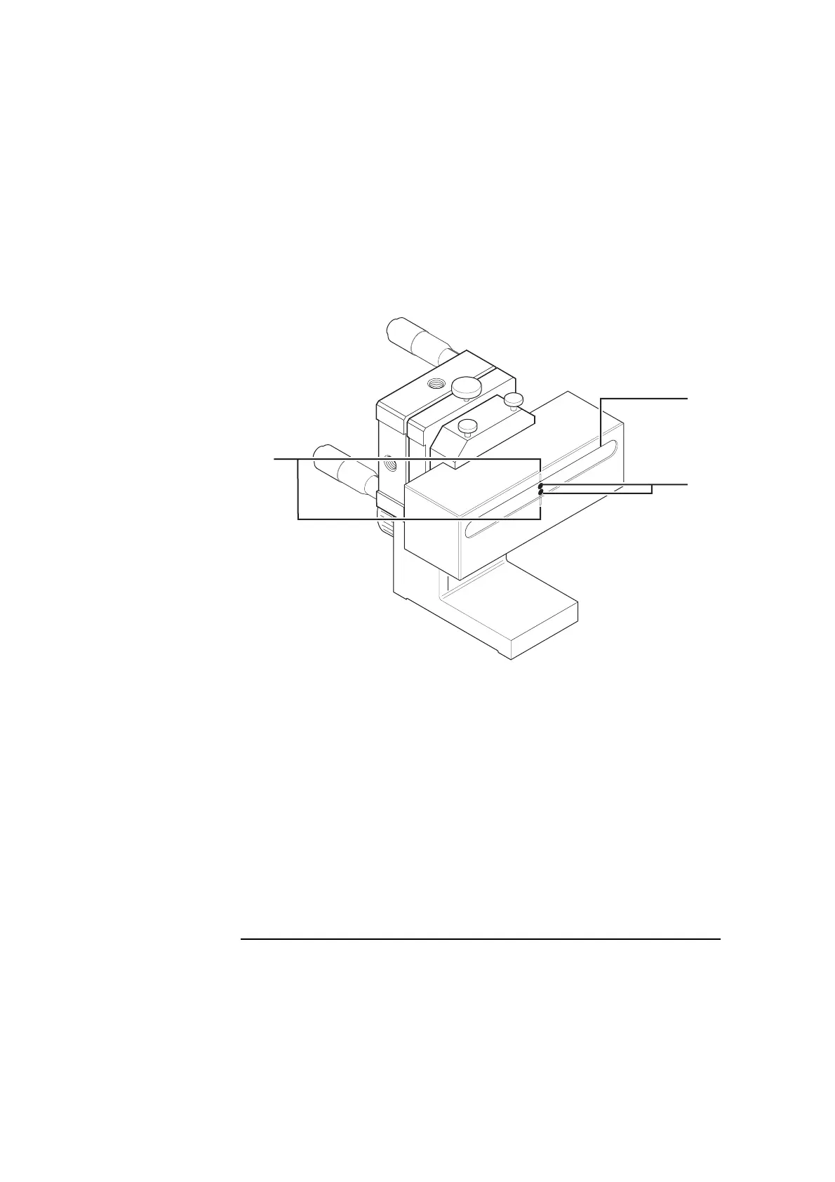
Figure 5-10. Initial position of the dots on the reflector
9 Set the laser head’s upper port to the small aperture and repeat step 8.
10 Secure the reflector assembly to the target machine using a clamp or
similar device so that the assembly remains perpendicular to the beam.
When using a clamp to secure the reflector assembly, make sure the base
does not rock.
11 Gently tap the reflector assembly to ensure that its mounting is rigid and
free of vibration.
If you feel any vibration, tighten all connections in the mounting.
1
Reflector’s slot
2 Two dots aligned
vertically
3 Midpoint notches
1
2
3
 Loading...


