Chapter 7 Squareness Measurements in a Vertical Plane
Mounting and Aligning Optics for the Second Axis Measurement
7-18 Measurements Reference Guide
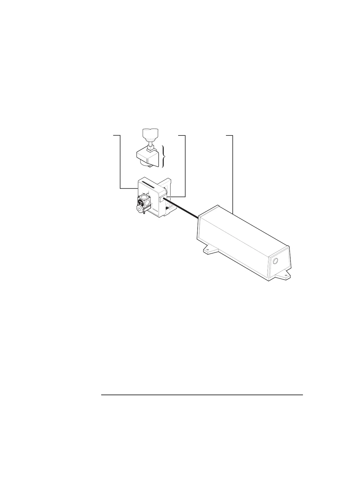
Figure 7-9. Gauge block attached to the side of the optical square
6 Turn the optical square left and right until the dot enters the upper port
on the laser head.
This makes the optical square perpendicular to the laser beam.
7 If you cannot get the dot to enter the upper port on the laser head, follow
these steps:
a. Remove the interferometer assembly from the spindle.
b. Mount a dial indicator in the spindle.
1
Optical square
2 Interferometer assembly
3 Gauge block
4 Laser head
3
1
4
2
OPTI
CA
L
SQ
U
AR
E
1
0777A
H
EW
L
E
T
T
-
P
A
C
K
A
R
D
9
0
1
0
7
7
2
A
T
U
R
N
I
N
G
M
I
R
R
O
R
H
E
W
L
E
T
T
-
P
A
C
K
A
R
D
1
A
1
0
7
7
2
-
6
7
00
2
A
S
SY
1
A
 Loading...


