Chapter 2 Linear Measurements
Mounting and Aligning the Optics on the Target Machine
2-14 Measurements Reference Guide
• Or, assemble and mount the retroreflector on the machine table as
shown in Figure 2-8.
NOTE If you plan on making a straightness or squareness measurement later,
position the top of the height adjuster even with the top of the post so you
can easily change optics. Then, use the adjustment knobs on the laser
head so the return beam enters the laser head’s lower port.
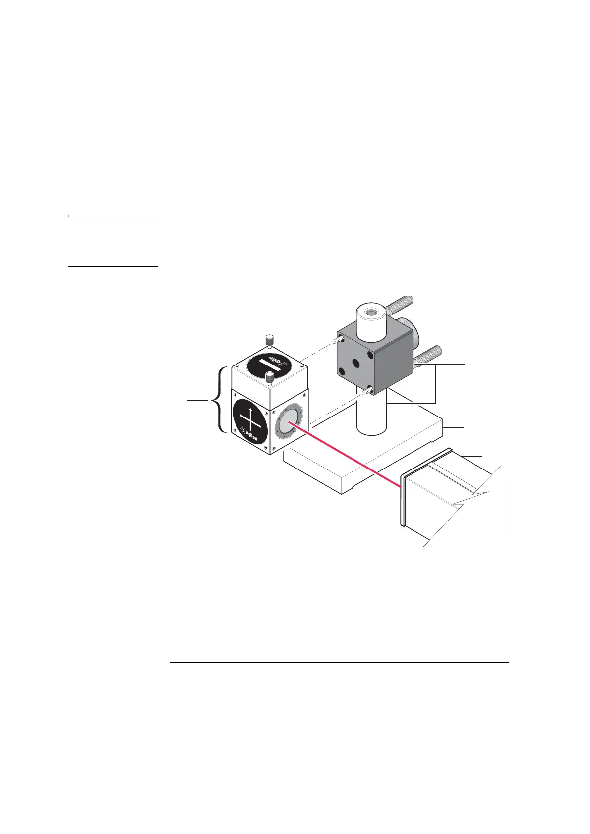
Figure 2-7. Interferometer assembly table mounting
1
Interferometer
assembly
2 Height adjuster and
post
3 Base
4 Laser head
1
0
7
8
5
A
H
E
I
G
H
T
A
D
J
U
S
T
E
R
A
1
2
3
4
1
0
7
6
6
A
L
I
N
E
A
R
I
N
T
E
R
F
E
R
O
M
E
T
E
R
1
0
7
6
7
A
L
I
N
E
A
R
R
E
T
R
O
R
E
F
L
E
C
T
O
R
1A