EasyManuals Logo

Agilent Technologies 5530 User Manual

Agilent Technologies 5530
378 pages
To Next Page IconTo Next Page
To Previous Page IconTo Previous Page
Page #37 background imageLoading...
Page #37 background image
Chapter 2 Linear Measurements
Mounting and Aligning the Optics on the Target Machine
Measurements Reference Guide 2-13
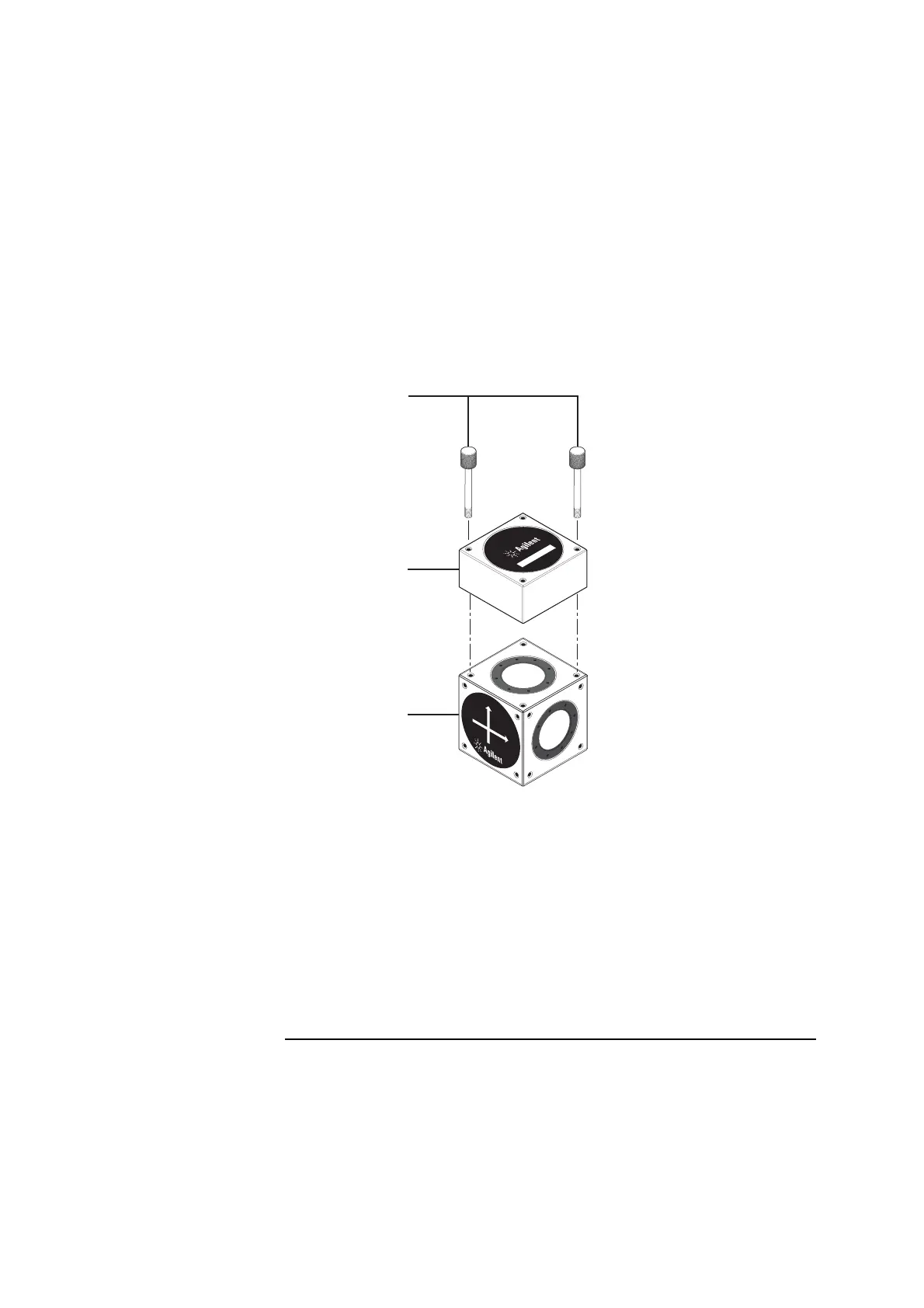
Figure 2-6. Assembling the interferometer assembly
6 Depending on the axis along which you are measuring, do one of the
following:
• Mount the interferometer assembly on the machine table as shown in
Figure 2-7. The arrow on the interferometer’s label that does not point
to the retroreflector must point to the external reflector; that is, away
from the laser head.
1
Knurled screws
2 Retroreflector
3 Interferometer
1
0
7
6
6
A
L
I
N
E
A
R
I
N
T
E
R
F
E
R
O
M
E
T
E
R
1
0
7
6
7
A
L
I
N
E
A
R
R
E
T
R
O
R
E
F
L
E
C
T
O
R
1A
1
2
3

Table of Contents

Other manuals for Agilent Technologies 5530

Questions and Answers:

Question and Answer IconNeed help?

Do you have a question about the Agilent Technologies 5530 and is the answer not in the manual?

Agilent Technologies 5530 Specifications

General IconGeneral
BrandAgilent Technologies
Model5530
CategoryTest Equipment
LanguageEnglish

Related product manuals