Chapter 2 Linear Measurements
Mounting and Aligning the Optics on the Target Machine
2-22 Measurements Reference Guide
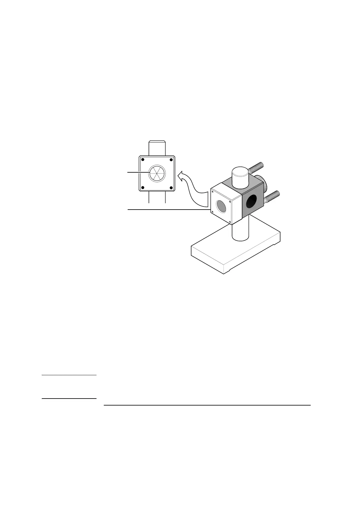
Figure 2-14. Correct retroreflector orientation
7 Move the retroreflector as close as possible to the interferometer assembly
without allowing the two to touch. Less than 25 mm (1 inch) is preferred.
Then, adjust the retroreflector so its return beam is centered on the target
covering the laser head’s return port and overlays the interferometer
return beam.
In the rest of this chapter, the position of the retroreflector near the
interferometer assembly as described above is referred to as the “start
position.”
NOTE To perform an alignment when the two optics are close together like this,
adjust the optics only, not the laser head. Adjust the laser head only when
the optics have been moved apart.
1
Correct orientation
of internal lines
2 Retroreflector
2
1
H
E
W
L
E
T
T
-
P
A
C
K
A
R
D
1
0
7
8
5
A
H
E
I
G
H
T
A
D
J
U
S
T
E
R
A