Chapter 4 Angular Measurements
Mounting and Aligning the Optics on the Target Machine
4-14 Measurements Reference Guide
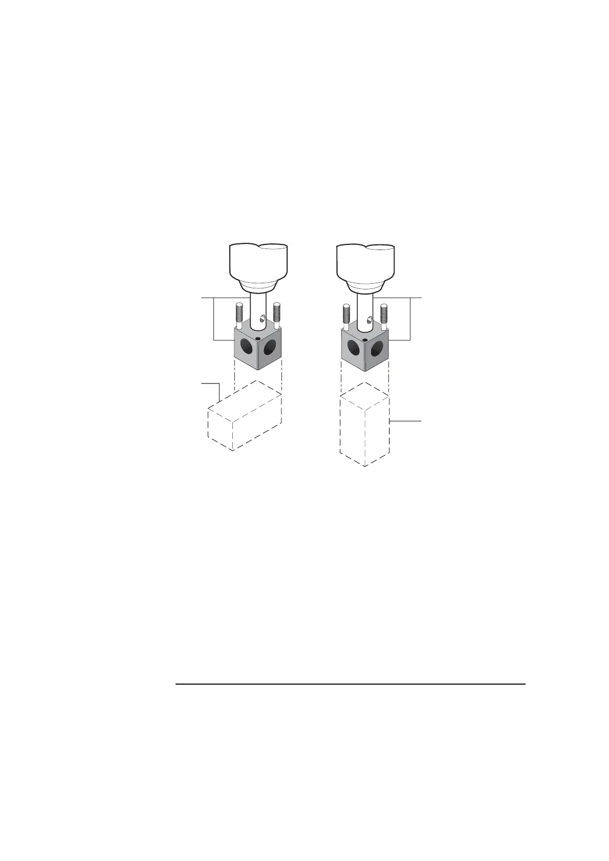
8 Mount the interferometer or reflector on the spindle as shown in
Figure 4-10.
Figure 4-10. Interferometer spindle mounting
Although posts, bases, and height adjusters provide considerable
adaptability for mounting optics, there may be some situations when you
need added flexibility. Figure 4-11 shows how you can increase
adaptability by using additional hardware.
9 Gently tap each optic with your finger to ensure its mounting is rigid and
free of vibration.
If you feel any vibration, tighten all connections in the mounting.
A
Mounting for Z-axis
pitch and yaw, or
X-axis and Y-axis
yaw
B Mounting for X-axis
and Y-axis pitch
************************
1 Post and height
adjuster
2 Angular
interferometer or
reflector
2
2
1
BA
1