Routine Maintenance: Detectors
Maintaining a flame ionization detector (FID)
Released: March 2004 6850 Series II GC User Information page 191 of 256
9. Unscrew the manifold block from the flow module.
10. Release the ribbon cable connector by pushing the two tabs and
disconnect it.
11. Unscrew the two front mounting screws, loosen the back screw, and
remove the flow module from the lid.
To install the flow module
1. Connect the ribbon cable to the flow module.
2. Attach the manifold block fitting.
3. Place the flow module into position and install it using the three mounting
screws.
4. Connect the three gas fittings and tighten.
5. Install the cover plates and tighten the mounting screws.
6. Replace the lid top cover.
7. To check performance, load the method which ignites the flame. Check
the offset. It must be between 5 picoamps and less than 20 picoamps after
the instrument has equilibrated.
Removing, inspecting, and replacing the jet
Jets require periodic cleaning or replacement. Even with normal use, deposits
develop in the jet (usually white silica from column bleed or black, carbon-
aceous soot). These deposits reduce sensitivity and cause chromatographic
noise and spikes. Although you can clean the jet, it is usually more practical to
replace dirty jets with new ones. If you do clean the jet, be very careful not to
damage it.
Your detector is shipped with a capillary column jet. If you are doing simulated
distillation or high-temperature runs, you must change the jet.
Load
RunNot Ready
Start
Stop
Prep Run
Ready for autoinject
Signal: FID 7.5

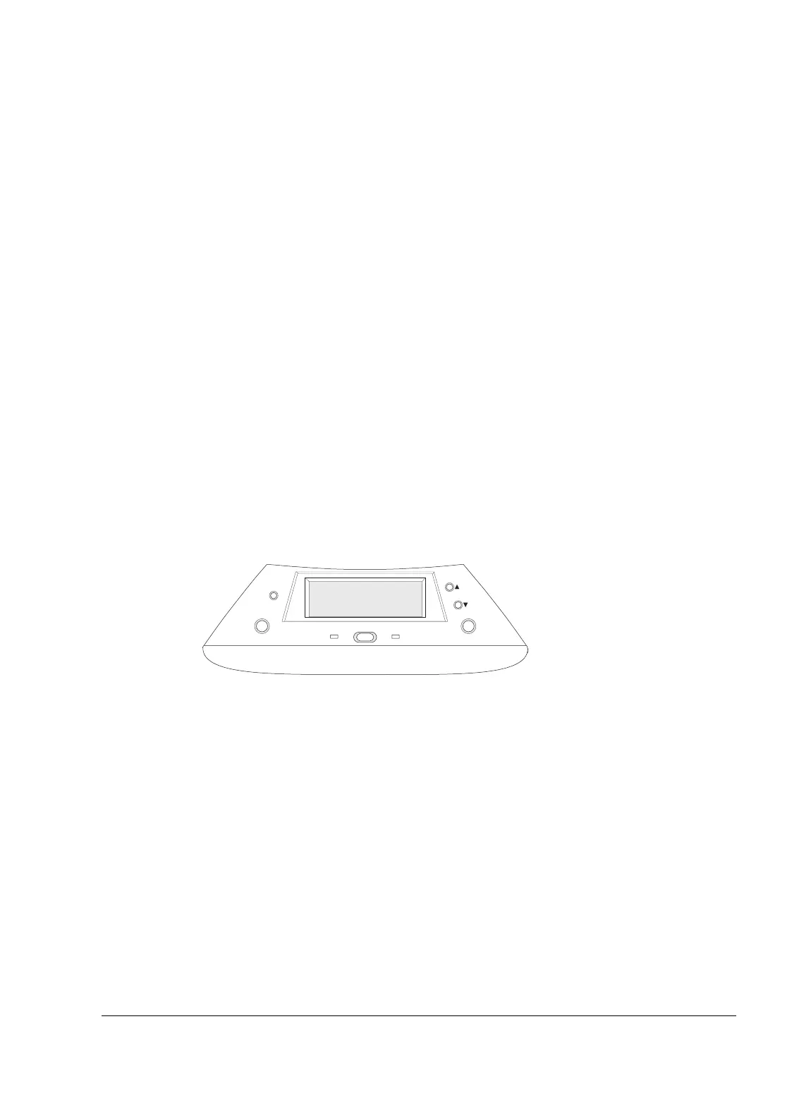 Loading...


