102 Agilent 8453 Dissolution Testing System Installing and Operating Manual
4 Using the Valve Unit and Valve-pump Controller
Servicing Your Valve System
Valve and Pump Actuation Electronics
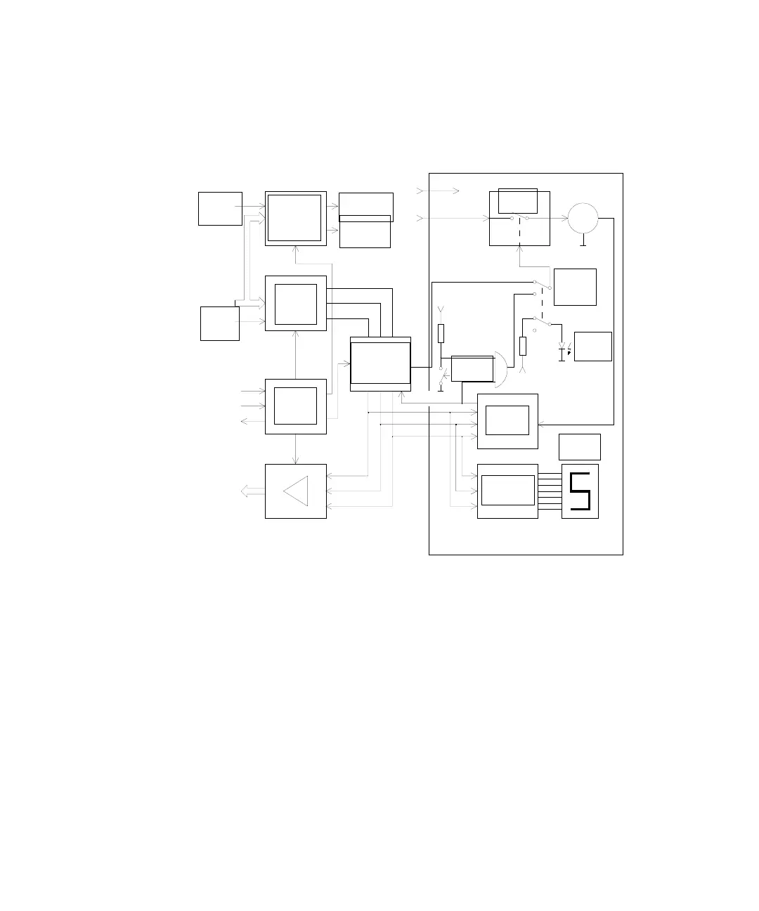
The block diagram, Figure 42, shows part of the valve-pump controller and the
electronics of the valve unit for channel 1 only. Pumps are not shown.
Control Logic
The control logic of the valve-pump controller performs the handshake with
the spectrophotometer, and defines the timing for the valve actuation, and for
data-in and data-out lines.
The data valid line DV(-) and read/write line R/W(-) from the GPI0 port of the
spectrophotometer are used for handshake. A “0” on the read/write line
indicates a write cycle of the spectrophotometer, that is address and data are
written into the valve-pump controller, see Figure 43.
Figure 42 Valve and Pump Actuation Electronics
channel 1
pump
select 1
data in
valve
select 1
DV (-)
R/W (-)
rdy (-)
data out
pump
drive
logic
valve
latch
control
logic
U1
pump on,
CCW
direction,
CW
+5V
24VAC
valve
position
comparator
run
position
+5V
Agilent 89079A
motor
switch
M
remote/
manual
switch
remote
LED
manual
advance
U2
+5V
position
encoder
7-segment
drivers
position
LED

 Loading...


