3-56 Service Guide
Adjustments and Correction Constants 8719ET/20ET/22ET
Raw Offset Correction Constants 8719ES/20ES/22ES
RF Network Analyzers
Raw Offset for the B Channel (ET Models)
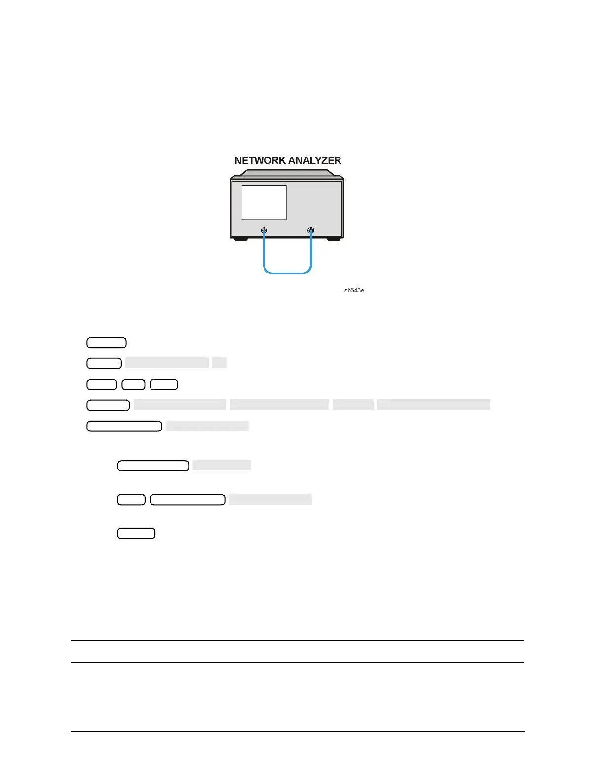
12.Connect the equipment as shown in Figure 3-15.
Figure 3-15 Setup for Calculating the Raw Offset for the B Channel (ET Models)
13.Press the following:
Note the frequency and write it down.
14.Press , and enter the maximum frequency point from
step 13.
Press . Note the maximum marker reading
(MMR) and write it down.
Press . Note the displayed test port power (TPP).
15.The objective is to set the maximum marker reading (MMR) to 4 dB higher than the
power meter reading. Perform the following mathematical operation.
a. Calculate the difference (∆) between the test port power meter reading (TPP) and the
maximum marker reading (MMR) and then add 4.
∆ = (TPP + 4) − MMR
NOTE The ∆ can be a positive or negative value.
16.If the magnitude of ∆ is less than 0.15 dB, then the offset for the B channel is correctly
set. Go to “Sampler Calibration Correction Constants (Test 51)” on page 3-58. If the
magnitude is greater than 0.15 dB, continue to the next step.
Preset
Meas
Stop 10 G/n
System
G/n
Power

 Loading...


