10-24 Service Guide
Service Key Menus and Error Messages 8719ET/20ET/22ET
Analog Bus on OFF 8719ES/20ES/22ES
RF Network Analyzers
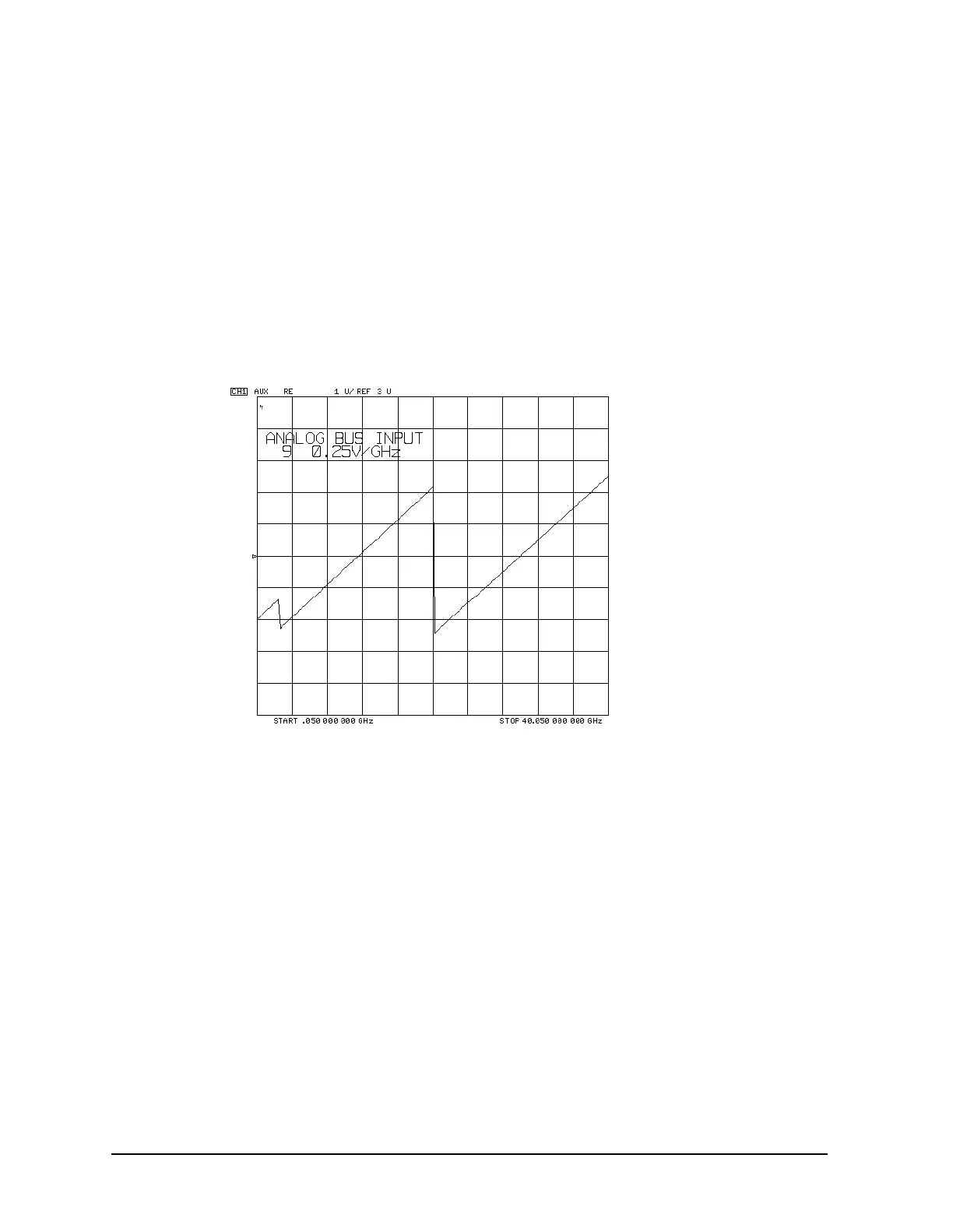
9. 0.25V/GHz (Source oscillator tuning voltage)
This node displays the tuning voltage ramp used to tune the source oscillators. You
should see a voltage ramp like the one shown in Figure 10-5. If this waveform is correct,
you can be confident that the A11 phase lock assembly, the source assemblies, the
A13/A14 fractional-N assemblies, and the A52 pulse generator are working properly
and the instrument is phase locked. If you see anything else, refer to Chapter 7 ,
“Source Troubleshooting.”
Figure 10-5 Node 9: 0.25V/GHz, Source Tuning Voltage
10.A11 Gnd (Ground reference)

 Loading...


