10-26 Service Guide
Service Key Menus and Error Messages 8719ET/20ET/22ET
Analog Bus on OFF 8719ES/20ES/22ES
RF Network Analyzers
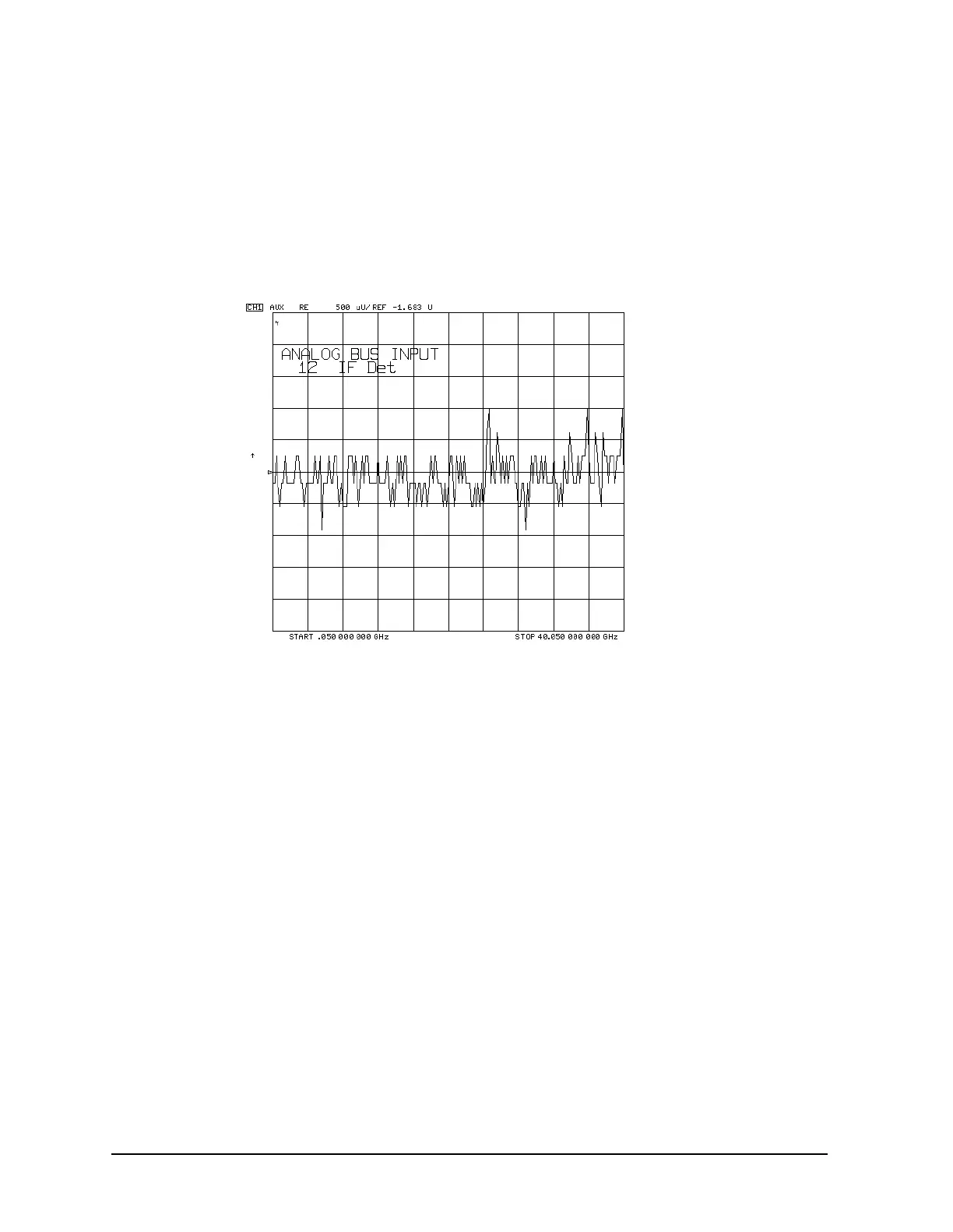
12.IF Det (IF on A11 phase lock after 40 MHz filter)
This node detects the IF as a voltage at the output of the 40 MHz filter on the A11 phase
lock assembly. The trace should be a flat line at about −1.7 V as shown in Figure 10-7.
Figure 10-7 Node 12: Typical IF Detector Voltage Trace
A12 Reference
13.Ext Ref (Rear panel external reference input)
This node is used to detect an external reference voltage. If an external reference
(timebase) is used, the voltage level should be about −0.6 V. If an external reference is
not used, the voltage level should be about −0.87 V.
14.100 kHz (100 kHz reference frequency)
Counter ON: analog bus
Reading: 0.100 MHz
This node counts the A12 100 kHz reference signal that is used on A13 (the fractional-N
analog assembly) as a reference frequency for the phase detector.
15.VCO Tune (A12 VCO tuning voltage)
This node displays the tuning voltage for the A12 VCO. It is used in the reference
assembly VCO tune adjustment.

 Loading...


