10-28 Service Guide
Service Key Menus and Error Messages 8719ET/20ET/22ET
Analog Bus on OFF 8719ES/20ES/22ES
RF Network Analyzers
A14 Fractional-N (Digital)
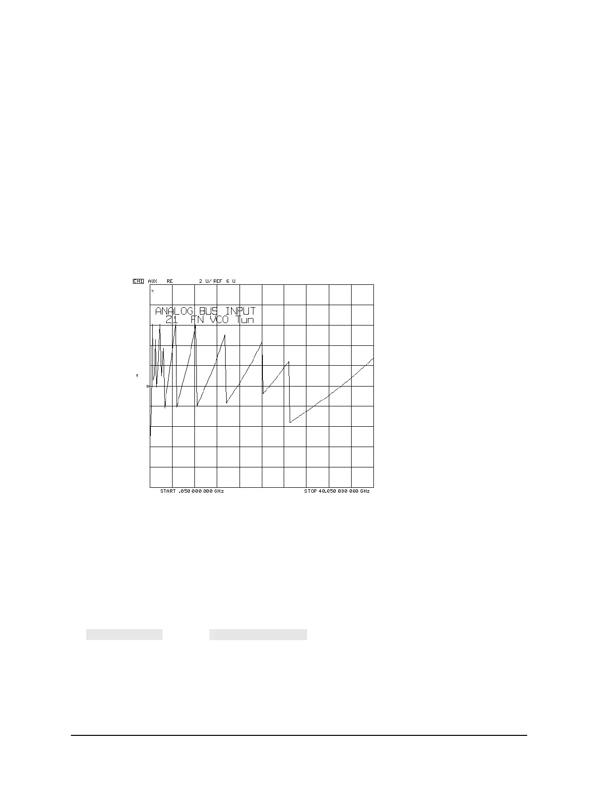
21.FN VCO Tun (A14 FN VCO tuning voltage)
This node displays the A14 FN VCO tuning voltage. This voltage comes from the A13
fractional-N (analog) assembly and is the return path for the fractional-N phase-locked
loop. If the A13 and A14 assemblies are functioning properly and the VCO is phase
locked, the trace should look like the trace shown in Figure 10-8 when in Log Freq.
sweep mode. Any other waveform indicates that the FN VCO is not phase locked. The
vertical lines in the trace indicate the band crossings. (The counter can also be enabled
to count the VCO frequency. Use CW mode.)
Figure 10-8 Node 21: FN VCO Tun, FN VCO Tuning Voltage
22.A14 Gnd (Ground reference)
23.Count Gate (Analog bus counter gate)
This node checks the analog bus counter gate signal. You should see a flat line at +5V.
The counter gate activity occurs during bandswitches, and therefore is not visible on the
analog bus. To view the bandswitch activity, look at this node on an oscilloscope, using
(refer to under the “Analog Bus Menu” heading).

 Loading...


