Service Guide 2-27
8719ET/20ET/22ET System Verification and Performance Tests
8719ES/20ES/22ES System Verification
RF Network Analyzers
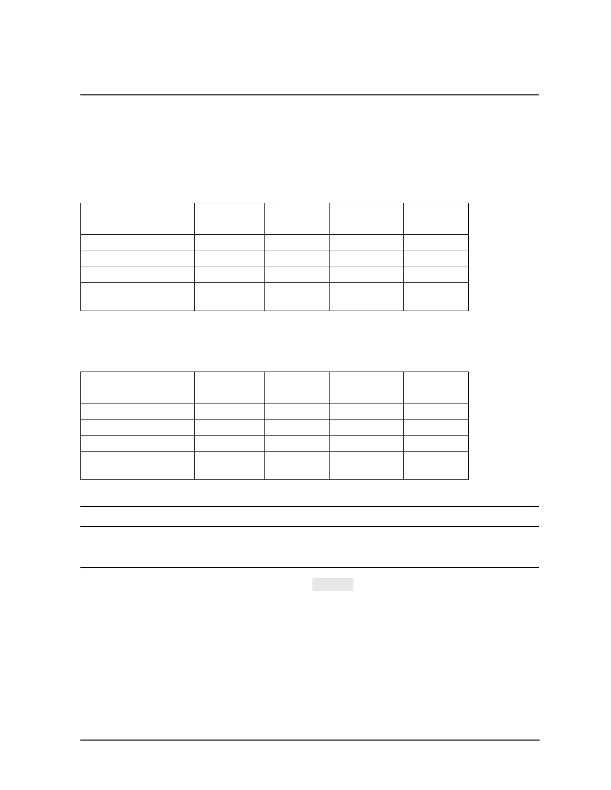
NOTE Although the performance for all four S-parameters on ES models are
measured, only the uncertainties associated with the items indicated in Table
2-4 will be used for the system verification. The other characteristics are less
important for verifying system performance and they will not appear on the
printout. If a measurement fails, note which device and S-parameter failed,
and continue on with the remaining tests.
On the ET models, two S-parameters are measured (S11 and S21). See
Table 2-5 for the uncertainties that are used for system verification.
NOTE Measured data is displayed as DATA.
Factory data is displayed as MEMORY.
4. When all measurements are complete, the softkey menu will appear.
Disconnect the verification device.
5. Enter Test 28 (using step keys, entry keys, or front panel knob). Repeat steps 1 through
4 in this section with the 40 dB attenuator (Ver Dev 2).
6. Enter Test 29 (using step keys, entry keys, or front panel knob). Repeat steps 1 through
4 in this section with the 50Ω airline (Ver Dev 3). For an example of how to perform
proper airline connections, refer to Figure 2-12 and Figure 2-13.
Table 2-4 Supported System Configurations for all ES Models
Verification Device S11/S22
Magnitude
S11/S22
Phase
S21/S12
Magnitude
S21/S12
Phase
20 dB attenuator x x x
40 dB attenuator x x x
Airline x x x x
Stepped impedance
airline
xxxx
Table 2-5 Supported System Configurations for all ET Models
Verification Device S11
Magnitude
S11 Phase S21
Magnitude
S21 Phase
20 dB attenuator x x x
40 dB attenuator x x x
Airline x x x x
Stepped impedance
airline
xxxx
TESTS

 Loading...


