1-110
Making Measurements
Using Test Sequencing
TTL Input Decision Making Five TTL compatible input lines can be used for decision making in test
sequencing. For example, if a test fixture is connected to the parallel port and has a micro switch that needs
to be activated in order to proceed with a measurement, you can construct your test sequence so that it
checks the TTL state of the input line corresponding to the switch. Depending on whether the line is high or
low, you can jump to another sequence. To access these decision making functions, press
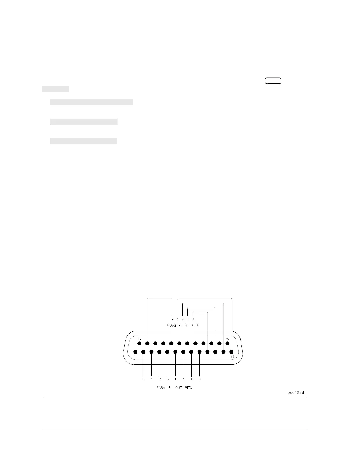
. Refer to Figure 1-80 for input bus pin locations.
lets you select the single bit (0 4) that the sequence will be looking
for.
lets you jump to another sequence if the single input bit you selected is in a
high state.
lets you jump to another sequence if the single input bit you selected is in a
low state.
Pin assignments:
• pin 1 is the data strobe
• pin 16 selects the printer
• pin 17 resets the printer
• pins 18-25 are ground
Electrical specifications for TTL high:
•volts(H) 2.7 volts (V)
• current = 20 microamps (A)
Electrical specifications for TTL low:
•volts(L) 0.4 volts (V)
• current = 0.2 milliamps (mA)
Figure 1-80 Parallel Port Input and Output Bus Pin Locations in GPIO Mode

 Loading...


