34 Agilent 1260 Infinity RID User Manual
1 Introduction to the Refractive Index Detector
Setting the 8-bit Configuration Switch (On-Board LAN)
Communication Settings for RS-232C
The communication protocol used in the column compartment supports only
hardware handshake (CTS/RTR).
Switches 1 in down and 2 in up position define that the RS-232C parameters
will be changed. Once the change has been completed, the column instrument
must be powered up again in order to store the values in the non-volatile
memory.
Use the following tables for selecting the setting which you want to use for
RS-232C communication. The number 0 means that the switch is down and 1
means that the switch is up.
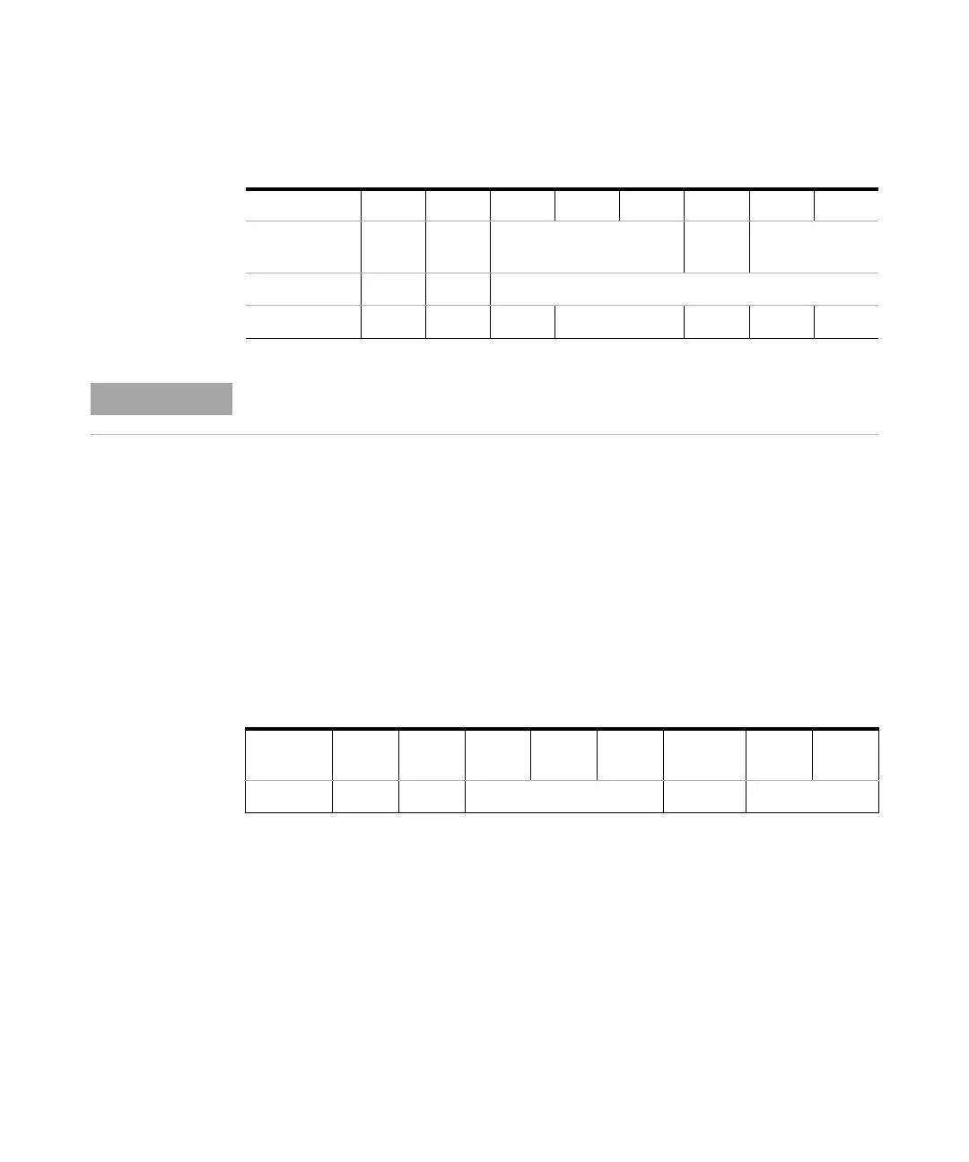
Tab le 5 8-bit Configuration Switch (without on-board LAN)
Mode Select12345678
RS-232C 0 1 Baudrate Data
Bits
Parity
Reserved 1 0 Reserved
TEST/BOOT 1 1 RSVD SYS RSVD RSVD FC
NOTE
The LAN settings are done on the LAN Interface Card G1369A/B. Refer to the
documentation provided with the card.
Tab le 6 Communication Settings for RS-232C Communication (without on-board LAN)
Mode
Select
12345 6 78
RS-232C 0 1 Baudrate Data Bits Parity