Page 36 VK 7025 Dissolution Apparatus Revision H, 11/10
Setup Operator’s Manual P/N 70-9033
Varian, Inc.
Installing Standard Evaporation Covers
To place the evaporation covers onto the spindles, complete the following steps:
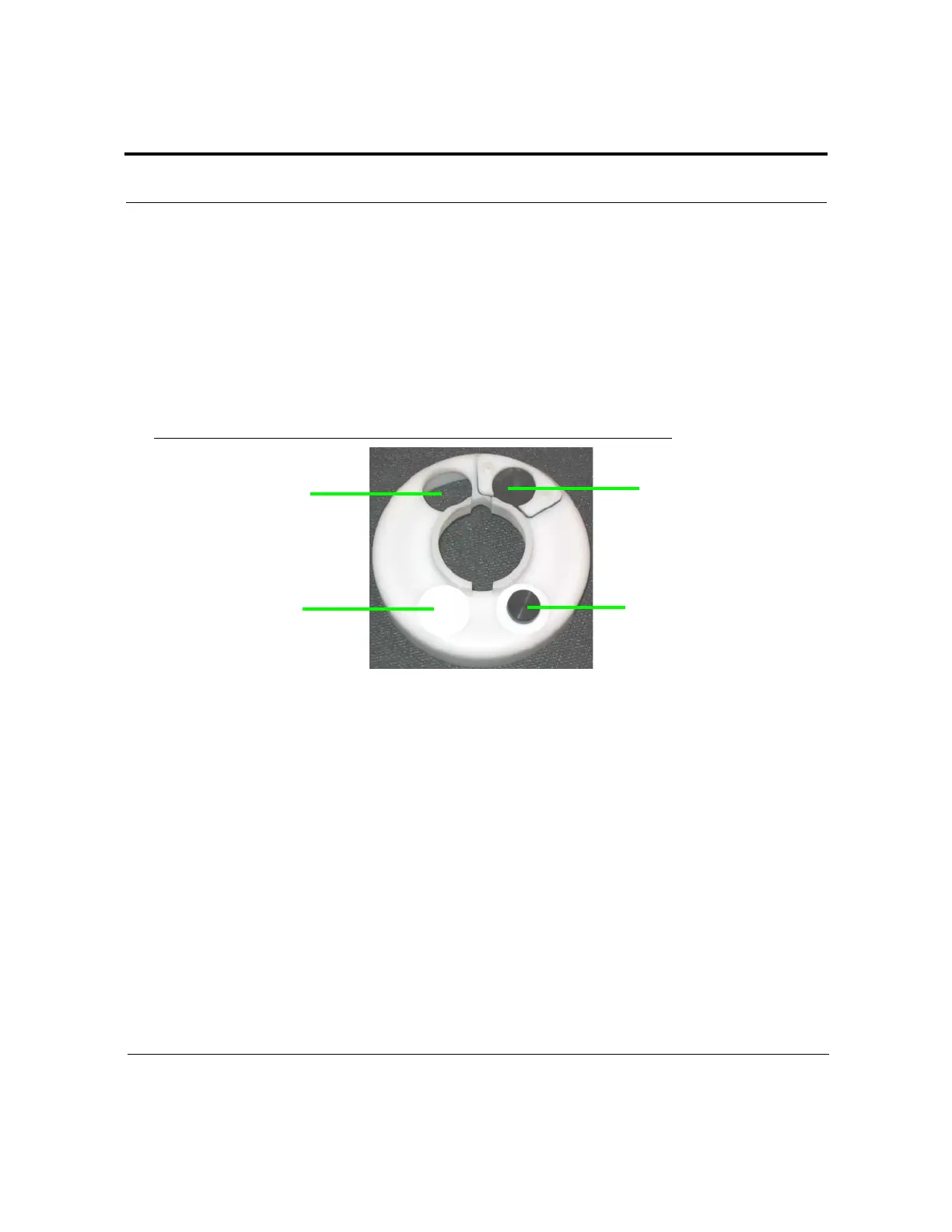
Step 1. For vessel position 1, place the knobbed evaporation plug in the left
manual sampling hole and the evaporation plug in the right manual
sampling hole (see Figure 8, “Standard Evaporation Cover,” below).
FIGURE 8. Standard Evaporation Cover
Step 2. Align the appropriate openings in the evaporation cover with the plastic
DDM tube extending from the bottom of the drive unit and the cannula
assembly.
Step 3. Apply gentle upward pressure until the top of the evaporation cover
slides over the O-ring on the spindle housing. The evaporation cover
floats in place.
Step 4. Repeat steps 1 - 3 for vessel positions 2 and 3.
Step 5. For vessel position 4, place the knobbed evaporation plug in the right
manual sampling hole and the evaporation plug in the left manual
sampling hole (see Figure 8, “Standard Evaporation Cover,” above).
Step 6. Repeat steps 2, 3, and 5 for the remaining vessel positions.
knobbed evaporation plug
evaporation plug in left
manual sampling hole
opening for DDM tube
opening for
cannula assembly
in right manual sampling hole
 Loading...
