Alfa Laval Micro
Installation, service and operating instruction
24
Info-button (7)
Operating with outdoor compensation, target room temperature is shown on the display
Press the Info-button to review:
target room temperature
error code, if any
measured supply water temperature
After ca. five seconds the display return to show measured room temperature.
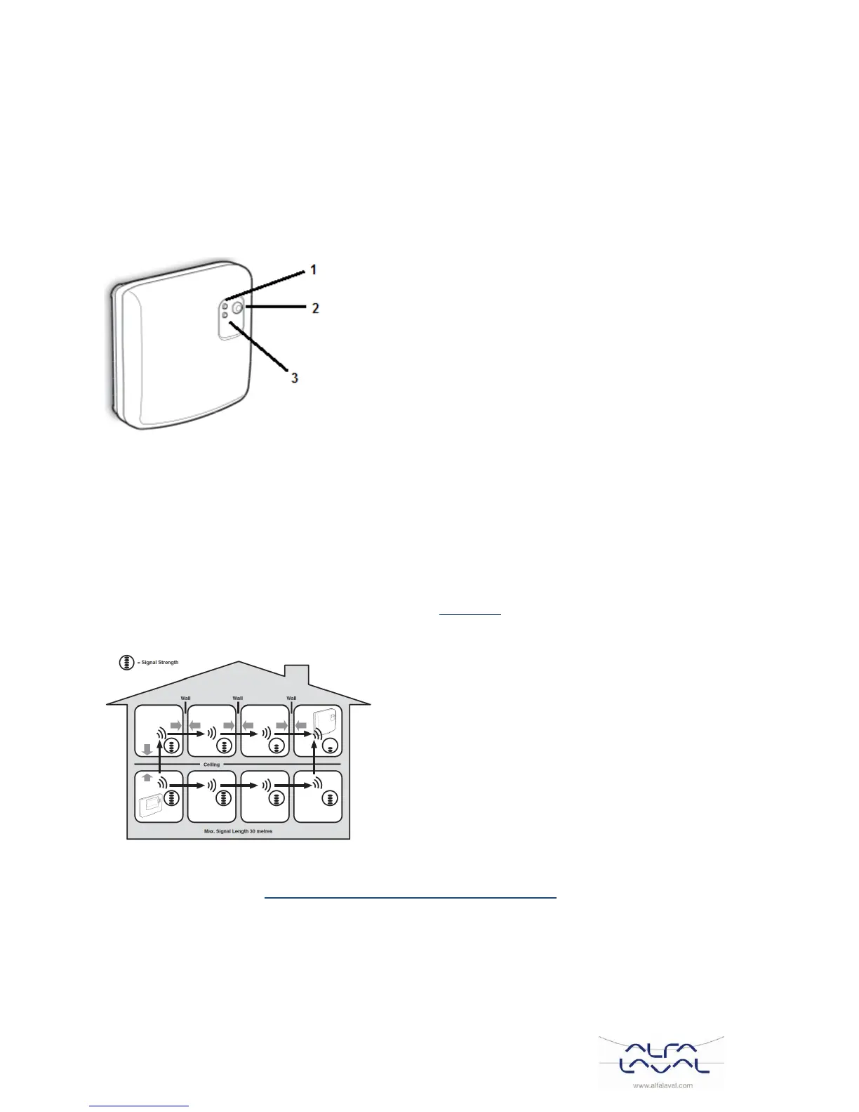
Relay box BDR91 6.3
1. Relay status indicator, green LED
2. Manually override button
3. Fault indicator, red LED
Installation information 6.4
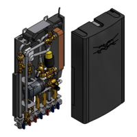
Special care must be taken during installation with product that communicates using RF technology.
The location of the RF components as well as the building structure may influence performance of the RF
system.
Within a typical residential building the two products should communicate reliably within a 30m range. It is
important to take into consideration that wall and ceilings will reduce the RF signal. The strength of the RF
signal reaching the relay box depends on the number of walls and ceilings separating it from the room
thermostat, as well as the building construction – see Picture 15 for an example of typical signal strength
reduction. Walls and ceilings reinforced with steel or plasterboard walls lined with metal foil reduce the RF
signal significantly more.
Picture 15
When a position is selected for the room thermostat, check the position using the RF Communication Test
mode, described in section 6.6.1 Locating and mounting the room thermostat. If the position is unsuitable the
relay box will not respond and an alternative position must be selected.