23
Chapter 1 Getting Started
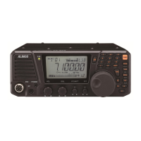
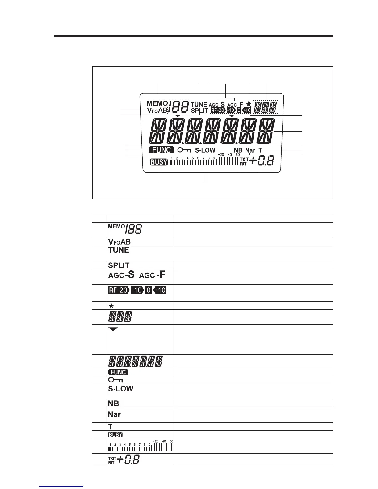
Display
(1) (3)
(2)
(7)
(18) (19)
(8)
(6)
(5)(9)
(17)
(10)
(16)
(14)
(15)
(11)
(13)
(12)
(4)
No. Key Function
(1)
Appears in the MEMORY mode, indicating the selected memory
channel.
(2)
Indicates the selected VFO mode A or B.
(3)
Appears while the external automatic antenna tuner is being
tuned.
(4)
Appears in the split-frequency operation.
(5)
AGC parameter, S for slow, F for fast.
(not in FM mode)
(6)
Indicates the receiver’s front-end gain or attenuation level.
(7)
Appears when a Multi-function key is activated.
(8)
Indicates the selected mode, including LSB, USB, CWL, CWU,
FM, AM and SET.
(9)
This cursor notifi es of the position you can change using the [M/
KHz] key.
Appears above the frequency digit you can change with the [UP/
DOWN] or [Ÿ/ź] keys.
(10)
Indicates the transmit/receive frequency.
(11)
Appears when a function key is activated.
(12)
Appears when the DIAL or key LOCK function is activated.
(13)
“LOW” appears when the output power is set to low.
“S-LOW” appears when the output power is set to supper low.
(14)
Appears when the NB (noise blanker) is activated.
(15) Appears when the narrow fi lter is used in the SSB, CW and AM
modes.
(16)
Appears during the tone encode operation. (FM mode only)
(17)
Appears when squelch is unmuted.
(18)
S meter: Indicates relative received signal strength
RF meter: Indicates relative output power level.
(19)
Indicates the TXIT or RIT shift frequency.
 Loading...