138 Rockwell Automation Publication 1783-UM007G-EN-P - February 2017
Chapter 5 Install Stratix 5700 Switches
Use at least 4 mm
2
(12 AWG) wire to connect to the external grounding screw.
The ground lug is not supplied with the switch. You can use one of the these
options:
• Single ring terminal
• Two single ring terminals
To ground the switch to earth ground, follow these steps. Be sure to follow any
grounding requirements at your site.
1. Use a Phillips screwdriver or a ratcheting torque screwdriver with a
Phillips head to remove the ground screw from the front panel of the
switch.
Store the ground screw for later use.
2. Use the guidelines from the manufacturer to determine the wire length
to be stripped.
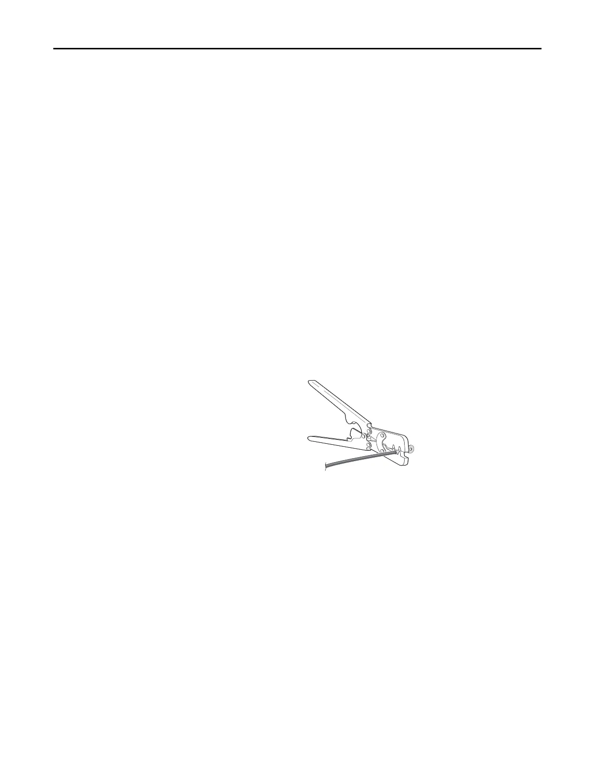
3. Insert the ground wire into the ring terminal lug and use a crimping tool
to crimp the terminal to the wire.
If you are using two ring terminals, repeat this action for the second ring
terminal.
4. Slide the ground screw through the terminal.
32273-M
 Loading...


