82 Rockwell Automation Publication 1783-UM007G-EN-P - February 2017
Chapter 3 Install Stratix 5400 Switches
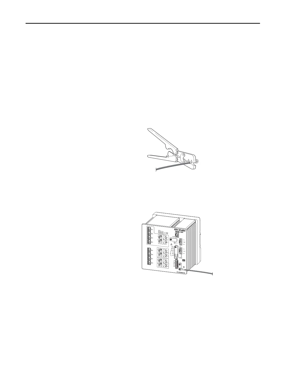
To ground the switch to earth ground, follow these steps. Be sure to follow any
grounding requirements at your site.
1. Use a Phillips screwdriver or a ratcheting torque screwdriver with a
Phillips head to remove the ground screw from the front panel of the
switch.
Store the ground screw for later use.
2. Use the guidelines from the manufacturer to determine the wire length
to be stripped.
3. Insert the ground wire into the ring terminal lug and use a crimping tool
to crimp the terminal to the wire.
If you are using two ring terminals, repeat this action for the second ring
terminal.
4. Slide the ground screw through the terminal.
5. Insert the ground screw into the functional ground screw opening on
the front panel.
6. Use a ratcheting torque screwdriver to tighten the ground screws and
ring terminal lugs to the switch front panel to 0.51 N
m (4.5 lbin).
Do not exceed the recommended torque.
7. Attach the other end of the ground wire to a grounded bare metal
surface, such as a ground bus, a grounded DIN rail, or a grounded bare
rack.
32515-M
Ring Terminal Lug
(single lug shown)
 Loading...


