84 Rockwell Automation Publication 1783-UM007G-EN-P - February 2017
Chapter 3 Install Stratix 5400 Switches
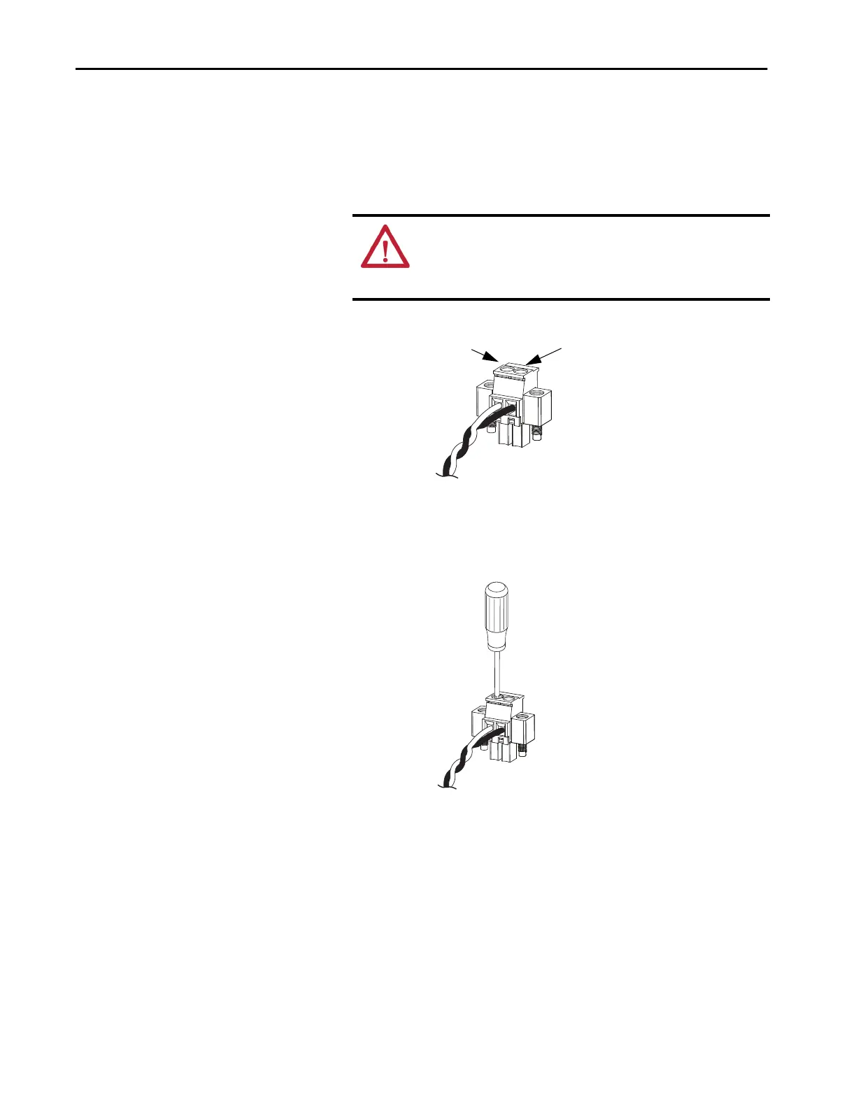
6. Insert the exposed part of the positive wire into the connection labeled
DC+ and the exposed part of the return wire into the connection
labeled DC-.
Be sure that you cannot see any wire lead. Only wire with insulation can
extend from the connector.
7. Use a ratcheting-torque screwdriver to torque the captive screws of the
power connector to 0.56 N•m (5.0 lb•in).
Do not exceed the recommended torque.
8. Connect the other end of the positive wire to the positive terminal on
the DC power source.
ATTENTION: An exposed wire lead from a DC input power source can
conduct harmful levels of electricity. Be sure that no exposed portion
of the DC input power source wire extends from the connectors or
terminal blocks.
32279-M
DC+
DC-
32281-M
 Loading...


