Publication 2098-IN003E-EN-P — April 2004
3-22 Connecting Your Ultra3000
Understanding Shunt
Connections
Follow these guidelines when installing and wiring your active or
passive shunt module/resistor.
Refer to Appendix B for the Ultra3000 interconnect diagrams.
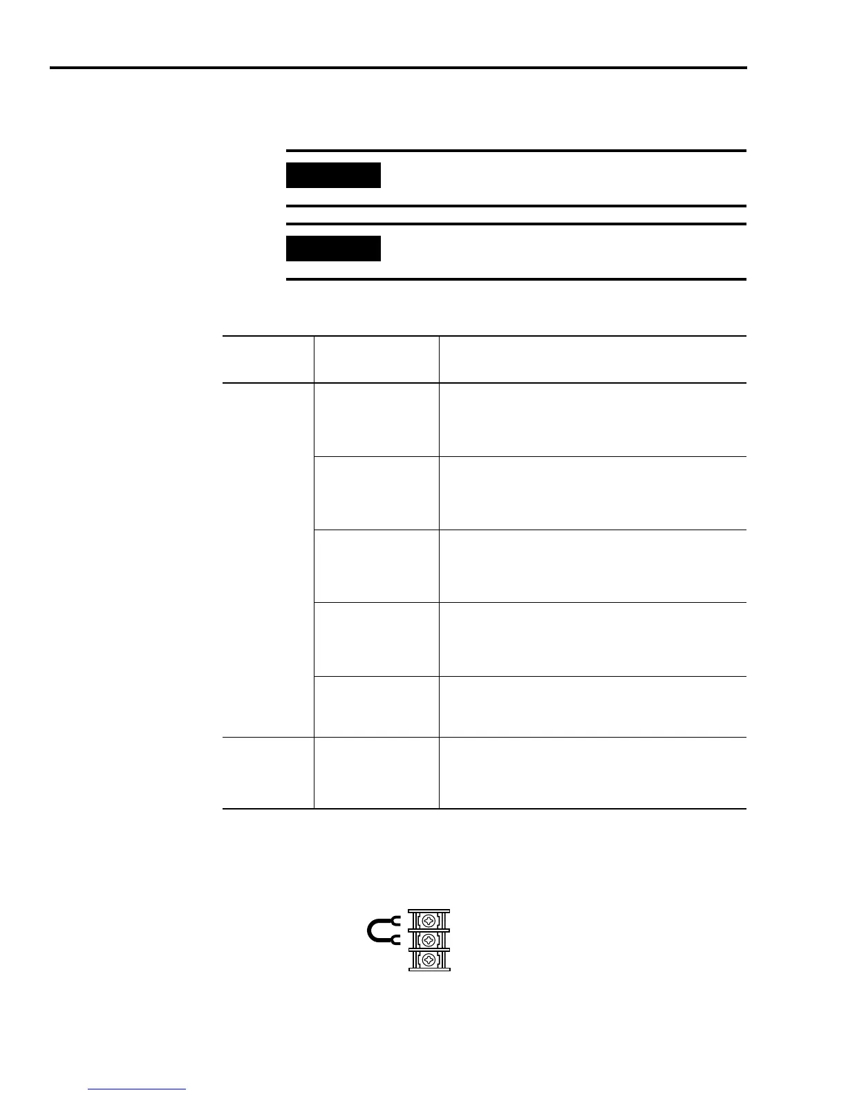
Figure 3.19
Connecting Your Shunt Resistor
1
This is the factory default jumper setting for TB2.
IMPORTANT
When tightening screws to secure the wires, refer to
the table on page 3-13 for torque values.
IMPORTANT
To ensure system performance, run wires and cables
in the wireways as established in Chapter 1.
If your
application
requires an:
And you are wiring to
this Ultra3000 drive:
Then refer to:
External Shunt
2098-DSD-005x-xx,
2098-DSD-010x-xx, or
2098-DSD-020x-xx
• Planning Your Panel Layout in Chapter 1.
• Figure B.5 on page B-7 of Appendix B.
• The installation instructions provided with your shunt
(publication 2090-IN002x-EN-P).
2098-DSD-030x-xx
• Planning Your Panel Layout in Chapter 1.
• Figure B.7 on page B-8 of Appendix B.
• The installation instructions provided with your shunt
(publication 2090-IN003x-EN-P).
2098-DSD-075x-xx, or
2098-DSD-150x-xx
• Planning Your Panel Layout in Chapter 1.
• Figures B.7 and B.8 on page B-8 of Appendix B.
• The installation instructions provided with your shunt
(publication 2090-IN001x-EN-P).
2098-DSD-HV030-xx,
-HV050-xx, or -HV100-xx
• Planning Your Panel Layout in Chapter 1.
• Figure B.7 on page B-8 of Appendix B.
• The installation instructions provided with your shunt
(publication 2090-IN004x-EN-P).
2098-DSD-HV150-xx, or
-HV220-xx
• Planning Your Panel Layout in Chapter 1.
• Fig
ure B.9 on page B-9 of Appendix B.
• The installa
tion instructions provided with your shunt.
Internal Shunt
2098-DSD-030x-xx,
2098-DSD-075x-xx,
2098-DSD-150x-xx,
2098-DSD-HVxxx-xx, or
2098-DSD-HVxxxX-xx
Verify the TB2 internal shunt jumper is in place between TB2-1
and TB2-2, as shown in Figure 3.19 below.
1
2
3
TB2
Connecting the Internal Shunt Resistor
1
 Loading...


