Publication 2098-IN003E-EN-P — April 2004
Ultra3000 Connector Data 2-45
Figure 2.45 shows the proper phasing of TTL A/B encoder signals
when positive current is applied.
Figure 2.45
Phasing of TTL A/B Encoder Signals
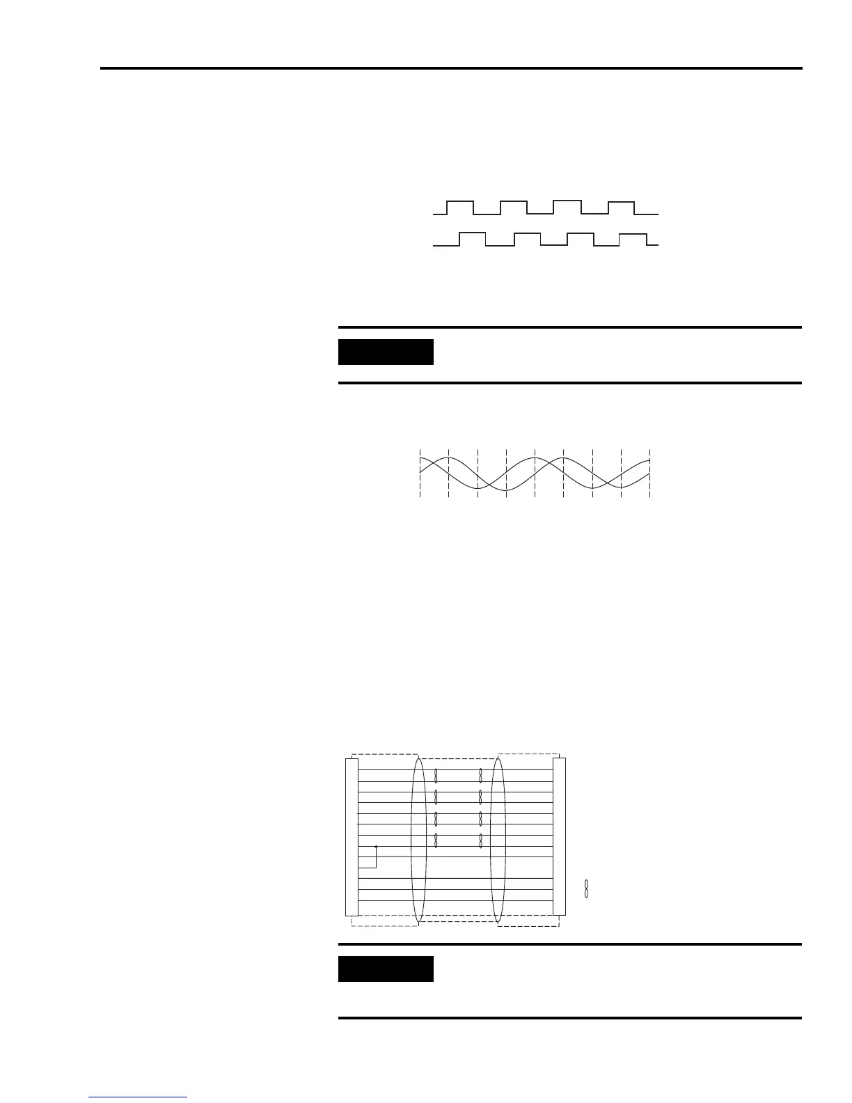
Figure 2.46 shows the proper phasing of Sine/Cosine encoder signals
when positive current is applied.
Figure 2.46
Phasing of Sine/Cosine Encoder Signals
Motor Encoder Connection Diagram
Figure 2.47 shows a typical wiring diagram of a motor feedback cable.
If the thermostat, limit, or Hall signals are not available, no
connections are required, but the drive must be configured through
software to ignore these signals. Refer to Appendix B for specific
Ultra3000 drive/motor interconnect diagrams.
Figure 2.47
Drive/Motor Wiring Diagram
A
B
IMPORTANT
Notice that the Sine/Cosine encoder signal phasing is
different than the phasing of the TTL encoders.
B
A
A+ or SIN+
A- or SIN-
B+ or COS+
B- or COS-
I+ or Data+
I- or Data-
POWER (+5V)
GROUND
TS+
TS-
S1
S2
S3
AM+
AM-
BM+
BM-
IM+
IM-
EPWR_5V
ECOM
TS
S1
S2
S3
1
2
3
4
5
10
14
6
11
12
13
8
Denotes twisted pair.
Connector backshell shielded 360° (both ends).
Encoder
Drive
IMPORTANT
Total resistance of the wiring for +5V encoder power
and ground connections between the drive and
motor must be less than 1.4 ohms.
 Loading...


