Publication 2098-IN003E-EN-P — April 2004
Connecting Your Ultra3000 3-19
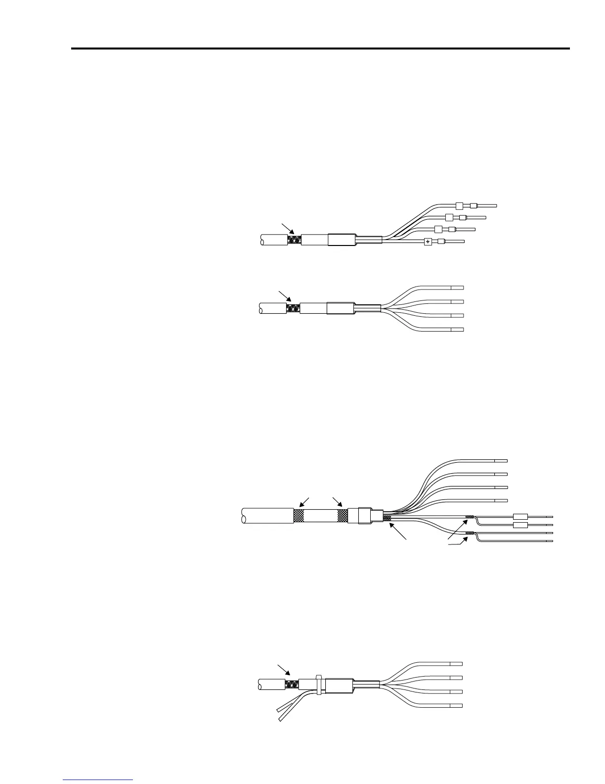
Wiring Motor Power
When using MP-Series (low inertia and integrated gear), 1326AB, and
F-, H-, or N-Series motors refer to Figure 3.16 for your motor power
cable configuration. Refer to Appendix B for the motor/drive
interconnect diagrams.
Figure 3.16
Motor Power Cable (MPL-A/B, MPG-A/B, 1326AB, and F-, H-, or N-Series Motors)
1
Motor cable leads (shortest to longest) are labeled differently, depending on the drive input voltage (230V/460V).
When using MP-Series (food grade) motors, the brake wires are
included in the motor power cable (2090-XXNPMF-xxSxx), as shown
in Figure 3.17. Refer to Appendix B for the motor/drive interconnect
diagram.
Figure 3.17
Motor Power Cable (MPF-A/B Food Grade Motors)
When using Y-Series motors, the brake wires are included in the
motor power cable (2090-XXNPY-16Sxx), as shown in Figure 3.18.
Refer to Appendix B for the motor/drive interconnect diagram.
Figure 3.18
Motor Power Cable (Y-Series Motors)
2090-XXNP
xx-xx
S
xx
2090-UXNPA/PB
xx-xx
S
xx
V
Exposed Braid
4 mm
2
(12 AWG) conductors or larger
1.5 or 2.5 mm
2
(16 or 14 AWG) conductors only
Black
Black
Green/Yellow
Green/Yellow
Brown
Blue
U or W
Brown or Blue
W or U
1
Blue or Brown
Exposed Braid
BR+
BR-
2090-XXNPMF
xx
S
xx
Cable Shield
(overall)
Brown
Black
Blue
Green/Yellow
Cable Shield
(for brake wires)
2090-XXNPY-16S
xx
Exposed Braid
Brake Wires
Green/Yellow
Black 1
Black 2
Black 3
Black 9
Black 7
 Loading...


