Publication 2098-IN003E-EN-P — April 2004
2-10 Ultra3000 Connector Data
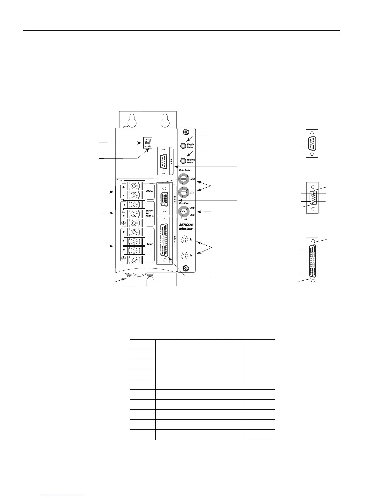
Ultra3000 (with SERCOS) Front Panel Connections
Use the figure below to locate the front panel connections on the
Ultra3000 with SERCOS interface 230V drives (500W, 1 kW, and 2 kW).
Figure 2.5
Ultra3000 Front Panel Connections for 2098-DSD-005-SE, -010-SE, and -020-SE
Serial Port Connector
The following table provides the signal descriptions and pin-outs for
the CN3 serial port (9-pin) connector.
Pin 11
Pin 6
Pin 15
Pin 1
Pin 10
Pin 5
Pin 30
Pin 44
Pin 1
Pin 15
Pin 16
Pin 31
Pin 6
Pin 9
Pin 1
Pin 5
8
CN1 44-pin
User I/O
Connector
CN2 15-pin
Motor Feedback
Connector
CN3 9-pin
Serial Port
Connector
Logic Power LED
Seven Segment
Status LED
DC Bus Connections for
Active Shunt Resistor Kit
AC Input Power
Connections
Motor Power
Connections
Module
Status LED
Network
Status LED
Node Address
Switches
Data Rate
Switch
SERCOS Interface
Receive (Rx) and
Transmit (Tx)
Connectors
Motor Power
Cable Shield Clamp
9-pin CN3
Serial Connector
15-pin CN2
Feedback Connector
44-pin CN1
I/O Connector
CN3 Pin Description Signal
1 RS-422/RS-485 Input+ RCV+
2 RS-232 Input RCV
3 RS-232 Output XMT
4 RS-422/RS-485 Output+ XMT+
5 Common COM
6Reserved –
7 RS-422/RS-485 Input- RCV-
8 RS-422/RS-485 Output- XMT-
9 Reserved –
 Loading...


