Publication 2098-IN003E-EN-P — April 2004
2-52 Ultra3000 Connector Data
Default Serial Interface Settings
The default setting of the Ultra3000 serial interface is as follows.
Figure 2.56
RS-232 Connection Diagram
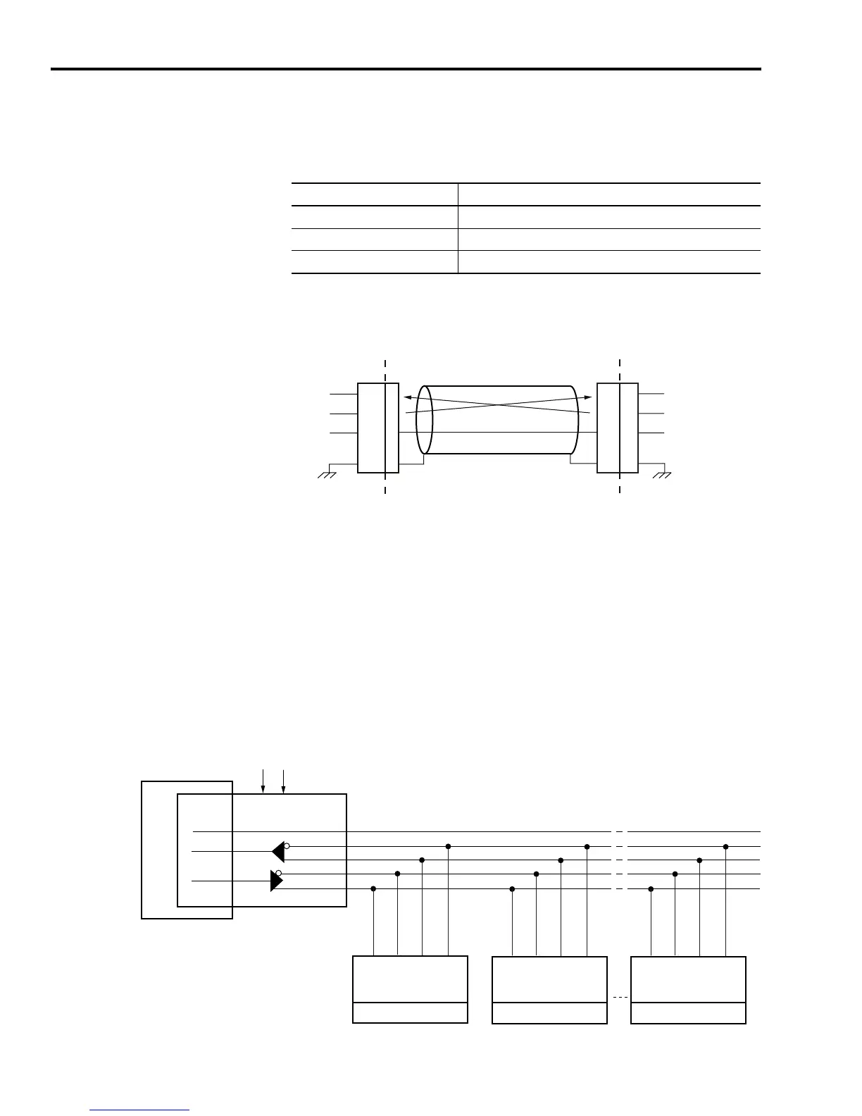
Multiple Axes RS-232 Communications
You can control multiple axes systems with a computer equipped with
an RS-232 serial port. An RS-232 serial communication port may be
converted to four wire RS-485 communication by attaching an RS-232
to four wire RS-485 converter. The figure below depicts the use of
such a device.
Figure 2.57
RS-232 to RS-485 Connection Diagram
Parameter Default Setting
Baud Rate 38,400
Frame Format 8 Data, No Parity, One Stop
Drive Address 0
2
3
5
2
3
5
2
3
5
RCV
XMT
COM
Note: PC pin-outs vary by
manufacturer.
USER PC
9-Pin
RS-232
9-Pin
Female
9-Pin
Male
Ultra3000 Drive
CN1 Connector
Drive Chassis
COM
RCV-
RCV+
XMT-
XMT+
7
5
17
3
14
COM
RS-232
Interface
PC
RCV
XMT
7
3
2
232 to 485
Adapter
+12V dc
Common
CN1
1
7
4 8
RCV+
RCV- XMT+
XMT-
CN1
1
7
4 8
RCV+
RCV- XMT+
XMT-
CN1
1
7
4 8
RCV+
RCV- XMT+
XMT-
Note: Pin-outs vary by manufacturer.
This example uses a B&B 485
adapter.
Drive 1
Drive 2
Drive n

 Loading...


