Publication 2098-IN003E-EN-P — April 2004
Connecting Your Ultra3000 3-23
Understanding Feedback
and I/O Cable Connections
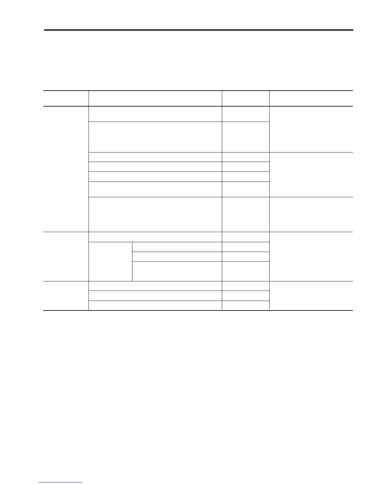
Factory made cables with premolded connectors are designed to
minimize EMI and are recommended over hand-built cables to
improve system performance. However, other options are available
for building your own feedback and I/O cables. Refer to the table
below for the available options.
1
This breakout board accepts 1 - 0.14 mm
2
(16 - 26 AWG) wire. For applications that require a 44-pin
drive-mounted breakout board that accepts 4 - 0.5 mm
2
(12 - 22 AWG) wire, contact your local Allen-Bradley
representative.
Drive Connector Connector Option
Option Catalog
Number
Reference
CN1
I/O Connector
44-pin drive-mounted breakout board with 24V to 5V auxiliary
power converter
2090-U3CBB-DM44
• CN1 Control Interface Breakout
Boards with 24V to 5V Auxiliary
Power Converter (publication
2090-IN008x-EN-P).
• Understanding Ultra3000 I/O
Specifications beginning on page
2-26.
12-pin drive-mounted breakout board with 24V to 5V auxiliary
power converter for SERCOS interface applications
2090-U3CBB-DM12
44-pin panel-mounted breakout board kit 2090-U3BK-D44xx
Understanding Ultra3000 I/O
Specifications beginning on page 2-26.
44-pin, drive-mounted breakout board.
1
2090-U3BB2-DM44
44-pin (high-density D-shell) drive connector kit 2090-U3CK-D44
Single-axis flying lead to 1756-M02AE module or 1784-PM02AE
PCI card
2090-U3CC-D44xx
Two-axis pre-wired to 1756-M02AE module 2090-U3AE-D44xx
• Understanding Ultra3000 I/O
Specifications on page B-20.
• Understanding Ultra3000 I/O
Specifications beginning on page
2-26.
CN2
Feedback Connector
Premolded cable at drive and motor end 2090-UXNFBxx-Sxx • The table below for your motor
feedback cable catalog number.
• Motor Feedback Connector Pin-outs
on page 3-24.
• Understanding Motor Encoder
Feedback Specifications beginning
on page 2-40.
Flying lead cable at
drive end
(2090-XXNFxx-Sxx)
15-pin drive-mounted breakout board 2090-UXBB-DM15
15-pin panel-mounted breakout board kit 2090-UXBK-DM15xx
15-pin (high-density D-shell) drive
connector kit
2090-UXCK-D15
CN3
Serial Connector
PC serial connector to premolded drive connector 2090-UXPC-DM09
Understanding the Serial Interface
beginning on page 2-51.
9-pin drive-mounted breakout board 2090-UXBB-DM09
9-pin (high-density D-shell) drive connector kit 2090-UXCK-D09
 Loading...


