Publication 2098-DU003B-EN-P — September 2006
Ultra3000 Digital Servo Drive Installation Manual 11
Page B-15
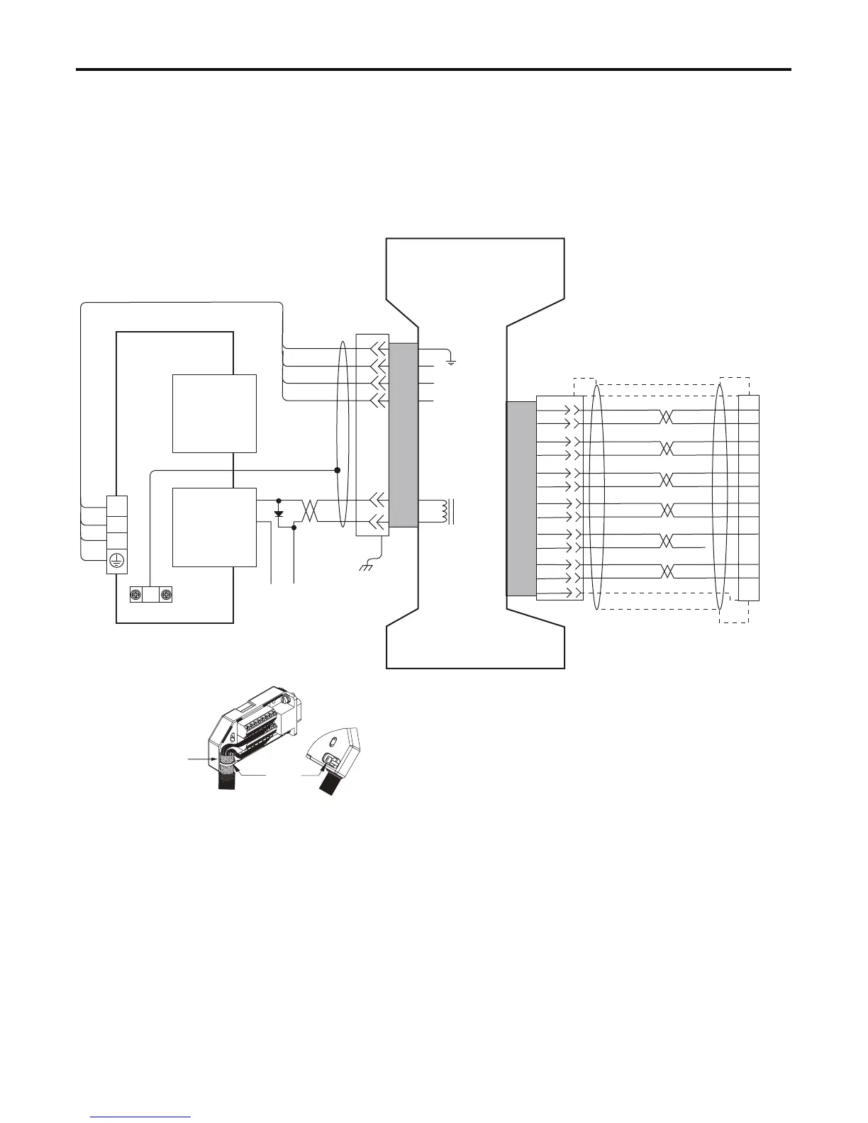
Replace Figure B.15 on page B-15 with the one shown below. The
new figure correctly identifies the motor power-cable pins as 1, 2, 3,
and 5. Also included is an illustration of grounding the feedback cable
shield.
Figure B.15
Ultra3000 Drive to Y-Series (230V) Motors
5
3
2
1
BR+
BR-
7
9
W
V
U
AM+
AM-
BM+
BM-
IM+
IM-
S1
S2
GREEN
WHT/GREEN
BLACK
WHT/BLACK
RED
WHT/RED
1
2
3
4
14
6
5
10
GRAY
WHT/GRAY
12
13
8
S3
–
WHT/BLUE
BLUE
BROWN
WHT/BROWN
22
23
24
9
10
11
12
13
14
15
17
19
–
+5VDC
ECOM
DRAIN
GND
43
44
+24V
COM
1-BLK
2-BLK
3-BLK
GN/YL
U
V
W
Motor
Brake
Motor
Power
TB1
Cable Shield
Clamp
Note 9
Note 19
Motor Feedback
(15-pin) Connector
CN2
Three-Phase
Motor Power
Motor
Feedback
User Supplied
+24V dc Power Supply
(1.0 A max)
2090-XXNFY-Sxx (flying lead)
or 2090-UXNFBY-Sxx (with drive-end connector)
Feedback Cable
Notes 12, 15, 16
Motor Feedback
(CN2) Connector
2090-XXNPY-16Sxx
Motor Power Cable
Note 12
Ultra3000 230V Drive
Note 13
BLK
BLK
Control Interface
(44-pin) Connector
CN1
Green/Yellow
3/Black
2/Black
1/Black
Y-Series (230V)
Servo Motors with
Incremental Feedback
Pigtail
Pigtail
Refer to illustration (lower left)
for proper grounding technique.
Motor Feedback Breakout Board
(2090-UXBB-DM15)
Grounding Technique for
Feedback Cable Shield
Exposed shield secured
under clamp.
Cable Tie
 Loading...


