Publication 2098-IN003E-EN-P — April 2004
Ultra3000 Connector Data 2-33
Figure 2.24
Drive Input Connected to PNP Transistor
Digital Outputs
There are four opto-isolated transistor outputs that can be configured
for a variety of functions through software. Additionally, the drive has
a relay output with normally open contacts. On SERCOS drives, the
relay output is dedicated as a Brake output, where closed contacts
release a motor brake.
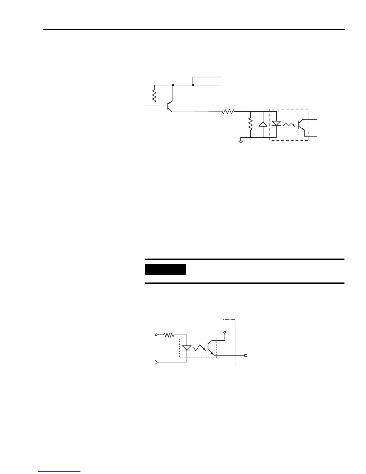
The configuration of the transistor outputs is shown in Figure 2.25,
and the configuration of the relay output is shown in Figure 2.26.
Figure 2.25
Transistor Output Hardware Configuration
2.7k Ω
1k Ω
CN1-31
through CN1-38
CN1-29
CN1-30
Ultra3000 Drive
IOCOM
IOPWR
IOPWR
IMPORTANT
There is no overload protection on the transistor
outputs.
200 Ω
+5V
OUTPUT
IOPWR
OUT
TLP127
Ultra3000 Drive
 Loading...


