Publication 2098-IN003E-EN-P — April 2004
2-38 Ultra3000 Connector Data
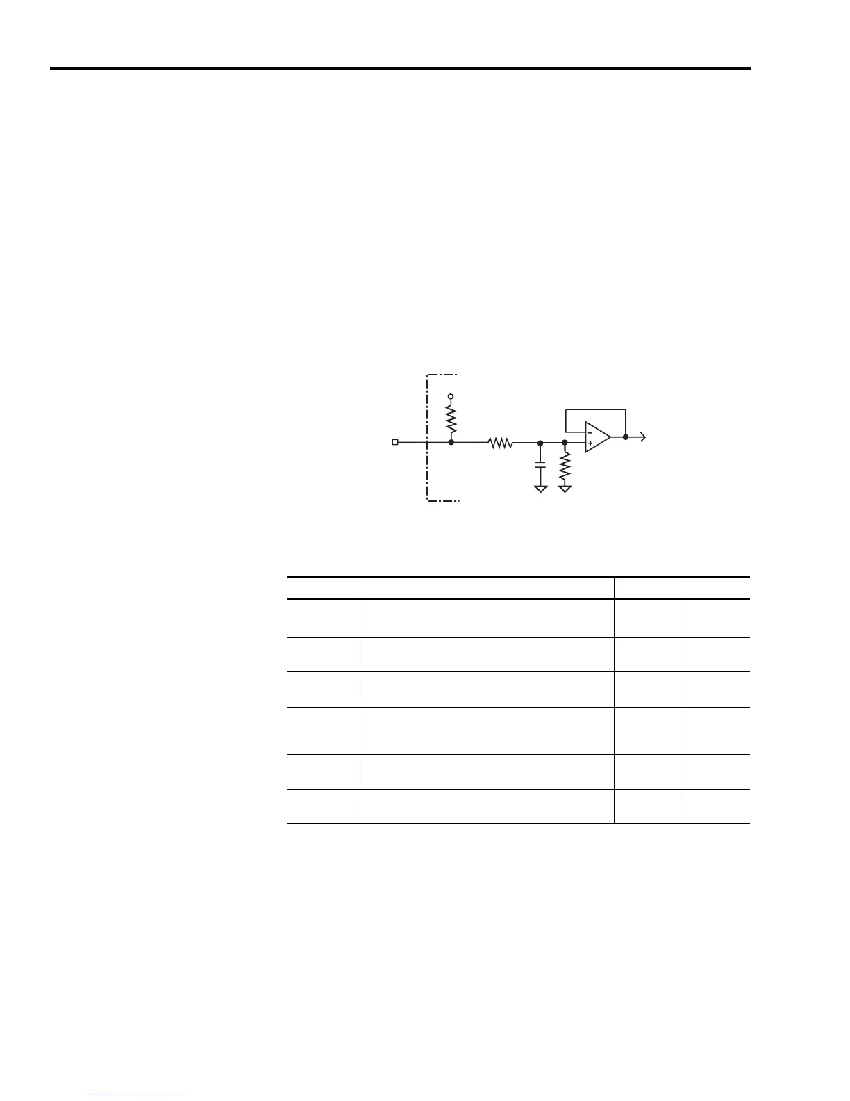
Analog ILIMIT Input
The ILIMIT input specifies to the drive if the drive output current
should be limited. If the ILIMIT input is not connected, current is not
limited. A 10 bit A/D converter digitizes the signal. The configuration
of the ILIMIT input is shown in Figure 2.35.
The input range is 0 to 10V, and the drive current is limited inversely
proportional to the input voltage. A +10V input corresponds to no
current limiting, and a 0V input prevents any drive current.
Figure 2.35
Analog ILIMIT Input Configuration
The following table provides a description of the analog ILIMIT input
specifications.
10k Ω
20k Ω
20k Ω
0.01
μ
F
+15 V
ILIMIT
Ultra3000 Drive
Parameter Description Minimum Maximum
Resolution
Number of states that the input signal is divided into
which is 2
(to the number of bits)
.
10 bits —
Input
Impedance
Open circuit impedance measured between the input
and analog common.
10 kΩ —
Input Signal
Range
Voltage applied to the input 0V +10V
Offset Error
Deviation from the correct value expected from
analog-to-digital conversion when 0V is applied to the
input.
—50 mV
Gain Error
Deviation of the transfer function from unity gain,
expressed in a percent of full scale.
—1%
Propagation
Delay
Delay from the input to the firmware-accessible
registers.
— 100 μS
 Loading...


