Publication 2098-DU003B-EN-P — September 2006
Ultra3000 Digital Servo Drive Installation Manual 9
Page B-12
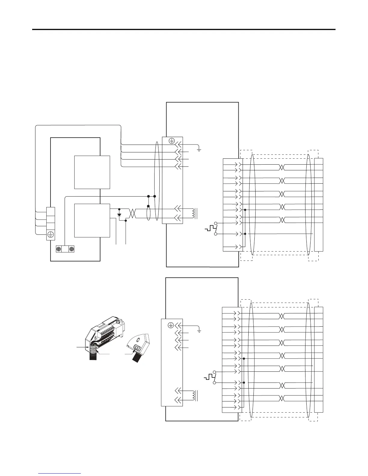
Replace Figure B.12 on page B-12 with the one shown below. The
new figure includes MP-Series food grade (MPF), stainless steel (MPS)
and low inertia (MPL-A/B15xx and MPL-A/B2xx) motors. Also
included is an illustration of grounding the feedback cable shield.
Figure B.12
Ultra3000 Drive to MP-Series (MPL-A/B, MPF-A/B, and MPS-A/B) Motors
BR+
BR-
W
V
U
GND
SIN+
SIN-
COS+
COS-
DATA+
DATA-
GREEN
WHT/GREEN
GRAY
WHT/GRAY
BLACK
WHT/BLACK
RED
WHT/RED
1
2
3
4
5
10
14
6
+9VDC
TS+
ORANGE
WHT/ORANGE
7
11
BR+
BR-
W
V
U
GND
+5VDC
ECOM
43
44
+24V
COM
U
V
W
3
4
5
6
1
2
9
10
14
12
11
13
D/
C/W
B/V
A/U
F/+
G/-
D/
C/W
B/V
A/U
F/+
G/-
BRN
BLK
BLU
GN/YL
TS-
COM
BLUE
AM+
AM-
BM+
BM-
IM+
IM-
+5VDC
ECOM
BLUE
WHT/BLUE
GREEN
WHT/GREEN
GRAY
WHT/GRAY
BLACK
WHT/BLACK
RED
WHT/RED
1
2
3
4
5
10
14
6
12
TS-
S1
–
TS+
ORANGE
WHT/ORANGE
11
S2
S3
COM
YELLOW
WHT/YELLOW
13
8
3
4
5
6
1
2
14
15
16
17
12
11
13
9
10
Motor
Brake
Motor
Power
TB1
Cable Shield
Clamp
Note 9
Note 19
Motor Feedback
(15-pin) Connector
CN2
Three-Phase
Motor Power
Motor Feedback
Thermostat
User Supplied
+24V dc Power Supply
(1.0 A max)
2090-XXNFMF-Sxx
(flying-lead) Feedback Cable
Notes 12, 16, 18
Motor Feedback
(CN2) Connector
2090-XXNPMF-xxSxx
Motor Power Cable
Note 12
Ultra3000 Drive
Notes 13, 14
Black
White
Control Interface
(44-pin) Connector
CN1
Green/Yellow
Blue
Black
Brown
Motor
Brake
Three-Phase
Motor Power
Motor Feedback
Thermostat
Motor Feedback
(CN2) Connector
MPL-A/B15xx and -A/B2xx,
MPF-A/Bxxx and MPS-A/Bxxx
Servo Motors with
High Resolution Feedback
MPL-A/B15xx and -A/B2xx
Servo Motors with
Incremental Feedback
Refer to illustration (lower left)
for proper grounding technique.
2090-XXNFMF-Sxx Feedback Cable
Note 12, 16
Refer to illustration (lower left)
for proper grounding technique.
Motor Feedback Breakout Board
(2090-UXBB-DM15)
Grounding Technique for
Feedback Cable Shield
Exposed shield secured
under clamp.
Cable Tie
 Loading...


