Publication 2098-DU003B-EN-P — September 2006
8 Ultra3000 Digital Servo Drive Installation Manual
Page B-6
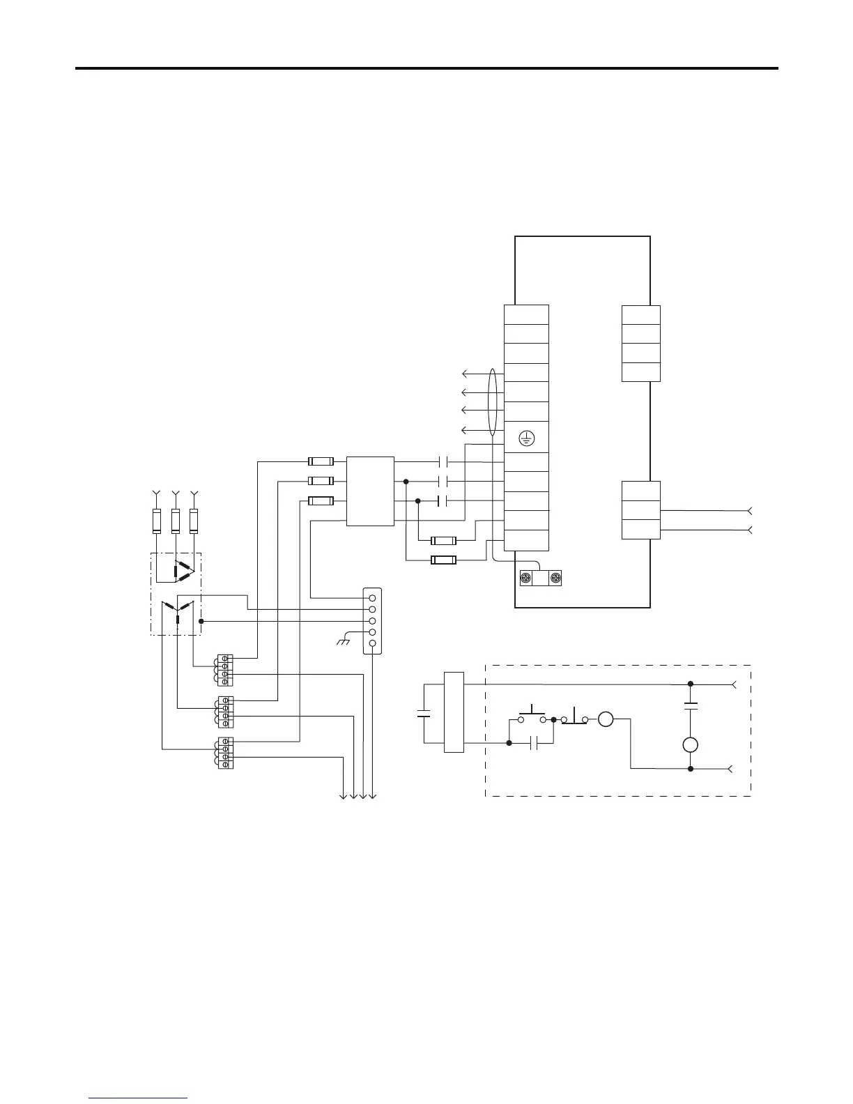
Replace the interconnect diagram on page B-6 with the one shown
below. The new diagram changes the recommended wiring of input
fusing, ac line filter, and contactor.
Figure B.4
Typical Power Wiring of Ultra3000 System
(2098-DSD-HVxxx-xx and -HVxxxX-xx)
TB1
DC+
DC-
W
V
U
L2
L3
CN1
43
44
L1
TB2
1
2
3
L3
L2
L1
L1 AUX
L2/N AUX
43
44
CN1
43
44
Ultra3000
Digital Servo Drives
2098-DSD-HVxxx-xx and
-HVxxxX-xx
Note 14
AC Input Power
Connections
Motor Power
Connections
Three-phase
AC Line Filter
Note 7
Three-phase Input
230-480V ac (rms)
Fused Disconnect
or Circuit Breaker *
Note 1
Isolation
Transformer *
Note 2
Chassis
Bonded Cabinet
Ground Bus *
Terminal Blocks *
Note 3
To additional
Ultra3000 drive.
Three-phase
Motor Power
Connections
Note 12
Cable Shield
Clamp
Note 9
STOP *
START *
CR1 *
CR1 *
CR1 *
M1 *
Refer to Attention statement (Notes 10, 11)
N.O. Relay Output+
N.O. Relay Output-
Note 20
24V dc
Neutral
M1 *
Note 8
External Passive
Shunt Connections
Input Fusing*
Notes 4 and 5
Three-phase AC Line
50/60 Hz
Note 6
Input Fusing *
Notes 4 and 5
* Indicates User Supplied Component
 Loading...


