Publication 2098-IN003E-EN-P — April 2004
B-16 Interconnect Diagrams
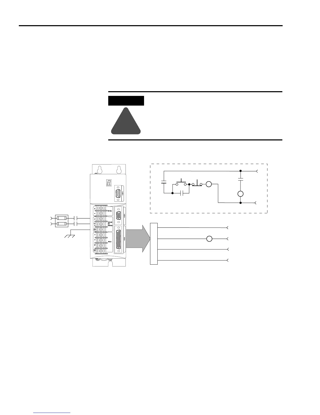
Control String Examples
(120V ac)
This section provides information to assist you in using the
configurable Drive Ready output in a control string with 120V ac input
voltage. Refer to Figure 2.26 in the chapter Ultra3000 Connector Data
for more information on the digital relay output.
The 120V ac control string wired to the Ultra3000 (2098-DSD-005x-xx,
-010x-xx, or -020x-xx) drives is shown in the figure below.
Figure B.16
120V ac Single-Phase Control String Example
ATTENTION
!
Implementation of safety circuits and risk assessment
is the responsibility of the machine builder. Please
reference international standards EN1050 and EN954
estimation and safety performance categories. For
more information refer to Understanding the
Machinery Directive (publication SHB-900).
CN1
Ultra3000
120V AC
50/60 Hz
STOP
START
CR1
CR1
CR1
M1
Refer to Attention statement above
CR2
43
44
3
2
CR2
24V DC
M1
Fuse
Block
Single-Phase
AC Line
50/60 Hz
L1
L2/N
N.O. Relay Output+
N.O. Relay Output-
Aux Logic Power In +5V
Aux +5V Common
From CN1 Breakout Board
with 24V to 5V Aux Power
Converter (2090-U3CBB-DM
xx
)
Note 20
Note 21
 Loading...


