Publication 2098-IN003E-EN-P — April 2004
Interconnect Diagrams B-13
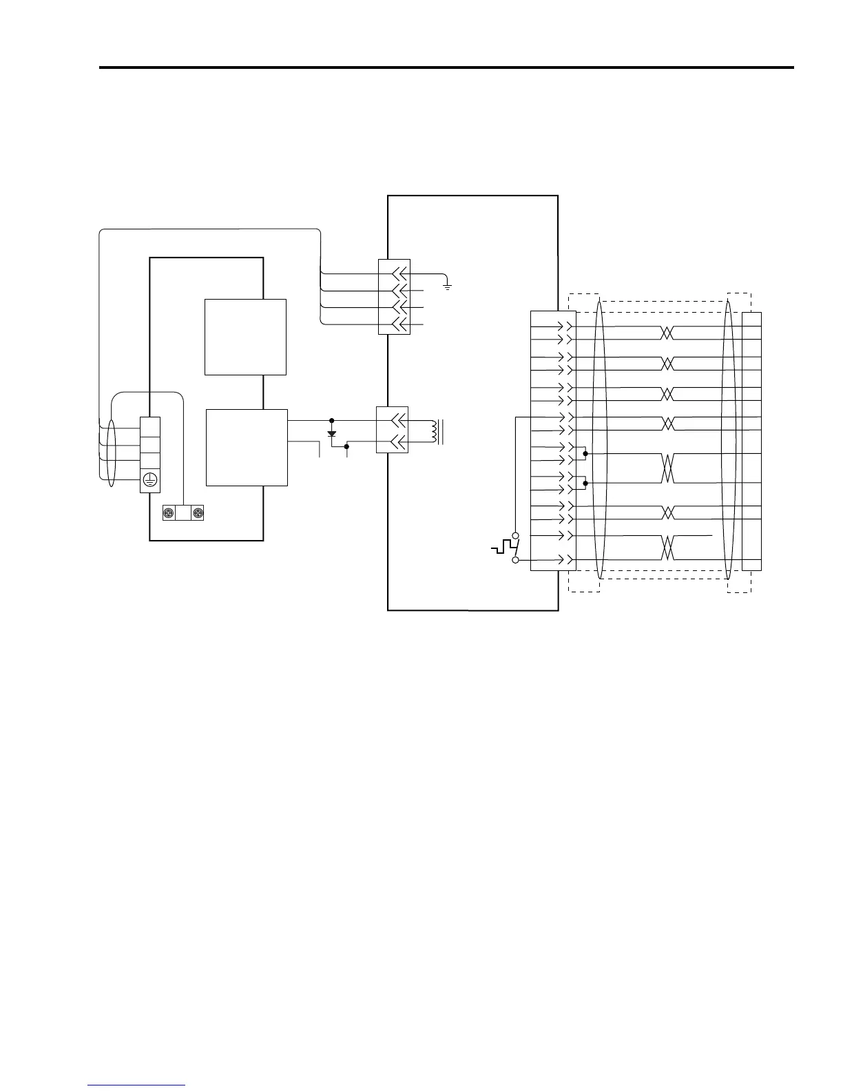
In the figure below, the Ultra3000 (230V) is shown connected to H-
and F-Series (230V) servo motors.
Figure B.13
Ultra3000 to H- and F-Series (230V) Motor Configuration
D
C
B
A
BR+
BR-
A
C
W
V
U
GND
43
44
+24V
COM
AM+
AM-
BM+
BM-
IM+
IM-
TS+
S3
GREEN
WHT/GREEN
GRAY
WHT/GRAY
BLACK
WHT/BLACK
RED
WHT/RED
C
D
E
F
A
B
R
P
1
2
3
4
5
10
11
8
K
J
L
M
+5VDC
ECOM
14
6
N
T
H
S
BLUE
WHT/BLUE
VIOLET
WHT/VIOLET
S2
S1
13
12
6
–
TS-
WHT/BROWN
BROWN
BRN
BLK
BLU
GN/YL
U
V
W
Motor Brake
Motor
Power
TB1
Cable Shield
Clamp
Note 9
Note 19
Motor Feedback
(15-pin) Connector
CN2
Three-Phase
Motor Power
Motor Feedback
Thermostat
9101-0330 Brake Cable Connector Kit
Note 12
User Supplied
+24V dc Power Supply
(1A max.)
2090-XXNFHF-Sxx (flying lead)
or 2090-UXNFBHF-Sxx (with drive-end connector)
Feedback Cable
Notes 12, 15, 16
Motor Feedback
(CN2) Connector
2090-XXNPH/HF-xxSxx or -UXNPBH/HF-xxSxx
Motor Power Cable
Note 12
Ultra3000 230V Drive
Note 13
Black
White
Control Interface
(44-pin) Connector
CN1
Green/Yellow
Blue
Black
Brown
H- or F-Series (230V)
SERVO MOTORS WITH
INCREMENTAL FEEDBACK
 Loading...


