Publication 2098-IN003E-EN-P — April 2004
Ultra3000 Connector Data 2-49
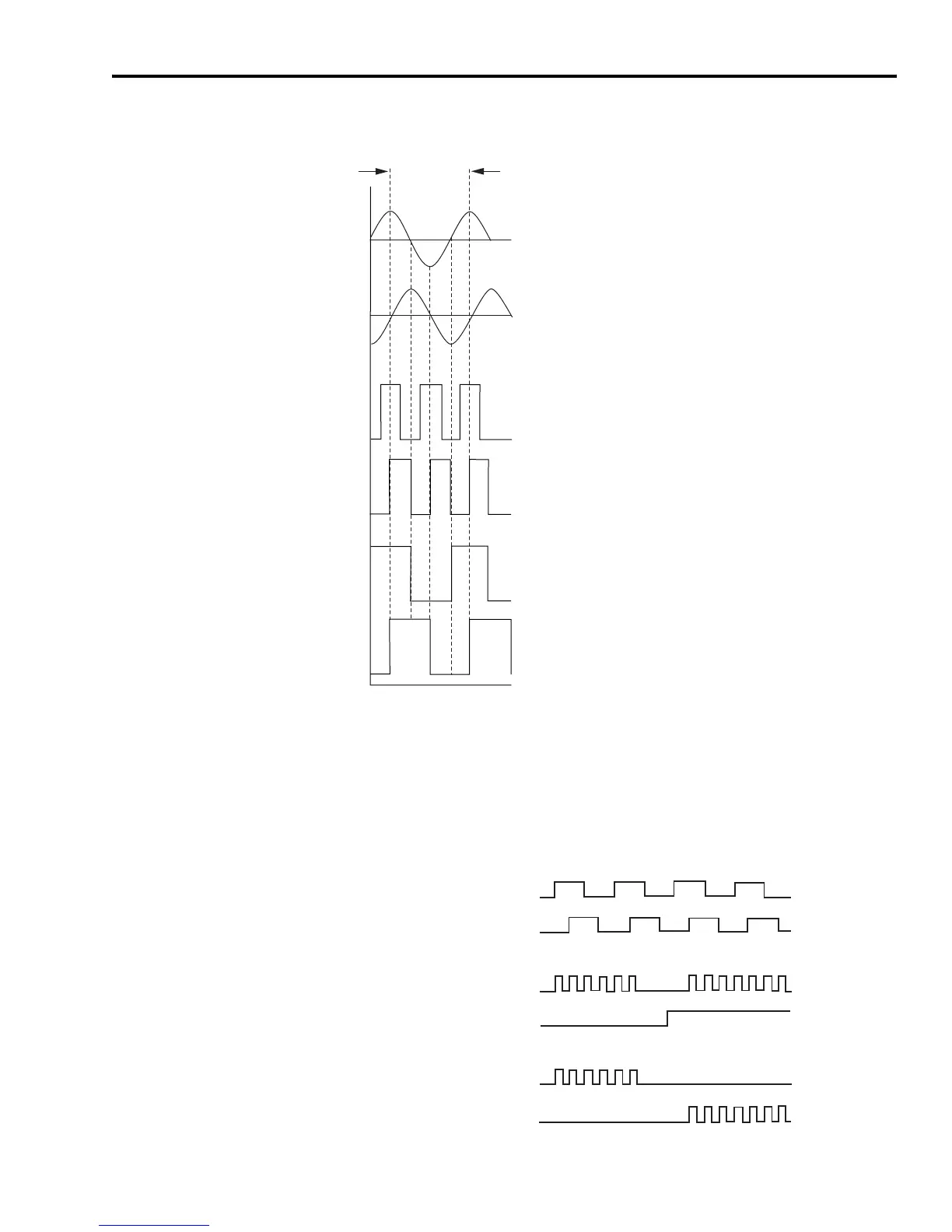
Figure 2.52
Interpolated and Divided Absolute High Resolution Encoder Counts
Understanding Auxiliary
Encoder Feedback
Specifications
The Ultra3000 can accept an auxiliary encoder signal of the following
types.
Figure 2.53
Auxiliary Encoder Input Signal Types
One
Cycle
Time
1
2
3
4
2
4
5
6
7
8
Voltage
6
8
1
3
5
7
2
4
1
3
Divided output from drive (divisor = 2)
Voltage
Voltage
CN1-10 (SIN/AM+) Unbuffered encoder feedback signal to drive, 1024 cycles/rev.
CN1-16 (SIN/AMOUT+) x8 Interpolated output from drive
CN1-18 (COS/BMOUT+) x8 Interpolated output from drive
CN1-12 (COS/BM+) Unbuffered encoder feedback signal to drive, 1024 cycles/rev.
STEP (CN1 pins 4 and 5)
DIRECTION (CN1 pins 6 and 7)
CW (CN1 pins 4 and 5)
CCW (CN1 pins 6 and 7)
A (CN1 pins 4 and 5)
B (CN1 pins 6 and 7)

 Loading...


