Publication 2098-IN003E-EN-P — April 2004
2-18 Ultra3000 Connector Data
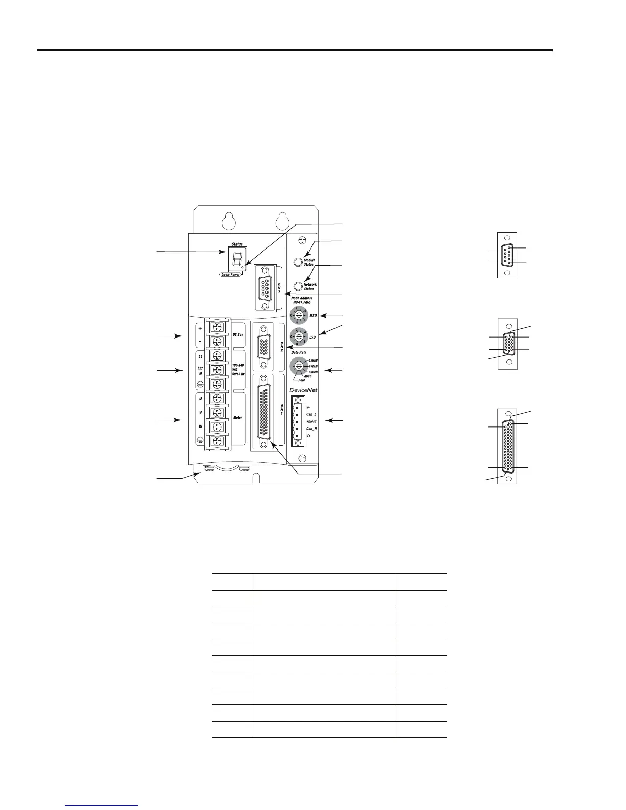
Ultra3000 (with DeviceNet) Front Panel Connections
Use the figure below to locate the front panel connections on the
Ultra3000 with DeviceNet Interface 230V drives (500W, 1 kW, and 2
kW).
Figure 2.9
Ultra3000 Front Panel Connections
for 2098-DSD-005-DN, -005X-DN, -010-DN, -010X-DN, -020-DN, and -020X-DN
Serial Port Connector
The following table provides the signal descriptions and pin-outs for
the CN3 serial port (9-pin) connector.
Pin 11
Pin 6
Pin 15
Pin 1
Pin 10
Pin 5
Pin 30
Pin 44
Pin 1
Pin 15
Pin 16
Pin 31
Pin 6
Pin 9
Pin 1
Pin 5
AC Input Power
Connections
Motor Power
Connections
DC Bus Connections for
Active Shunt Resistor Kit
Seven Segment
Status LED
Logic Power LED
CN3 9-pin
Serial Port
Connector
CN2 15-pin
Motor Feedback
Connector
CN1 44-pin
User I/O
Connector
DeviceNet Interface
Connector
Node Address
Switches
Data Rate Switch
Module Status LED
Network Status LED
Motor Power
Cable Shield Clamp
9-pin CN3
Serial Connector
15-pin CN2
Feedback Connector
44-pin CN1
I/O Connector
CN3 Pin Description Signal
1 RS-422/RS-485 Input+ RCV+
2 RS-232 Input RCV
3 RS-232 Output XMT
4 RS-422/RS-485 Output+ XMT+
5 Common COM
6Reserved –
7 RS-422/RS-485 Input- RCV-
8 RS-422/RS-485 Output- XMT-
9 Reserved –

 Loading...


