Publication 2098-IN003E-EN-P — April 2004
2-46 Ultra3000 Connector Data
Understanding Motor
Feedback Signals and
Outputs
The Ultra3000 is compatible with motors equipped with both
incremental A quad B or high resolution (Stegmann Hiperface
®
)
SIN/COS encoders.
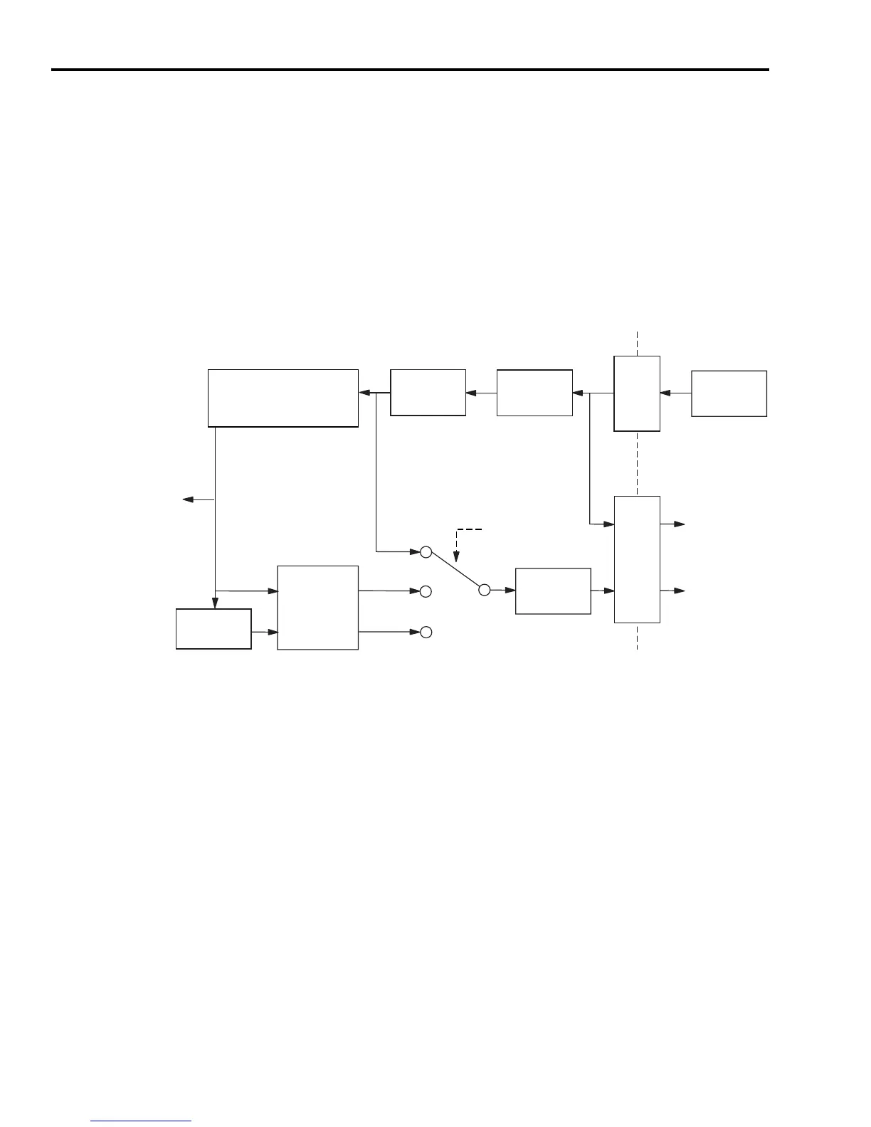
The buffered motor encoder outputs use RS-485 differential drivers
and have a maximum signal frequency of 2.5 MHz. The drivers can
drive a 2V differential voltage into a 100 ohm load. Use the block
diagram below to follow the motor encoder input through CN2 to the
buffered and unbuffered outputs on CN1.
Figure 2.48
Motor Encoder Outputs
1
Interpolation and division operations are performed in firmware and the resulting output frequency is updated at
250 μs intervals.
2
Interpolated and divided output not available on SERCOS drives.
Unbuffered Encoder Outputs
The unbuffered outputs available from the drive (CN1-10 through -15)
are tied directly to the incoming (incremental or high resolution)
encoder signals (CN2-1 through -6). The unbuffered outputs are not
filtered or conditioned.
TTL: x4
Sin/Cos: x4 to x1024
CN1
CN2
Filtering
Differential
Receivers
Motor
Encoder
Differential
Drivers
Interpolation
1
Division
1
Frequency
Limit
(0.5 to 8 MHz)
Buffered
Interpolated
2
Divided
2
Selected
Output
Type
Ultra3000 Drive
Buffered
Encoder
Output
Unbuffered
Encoder
Output
Position
Feedback
TTL or A quad B (incremental)
If (A leads B) in
(A leads B) out
SIN/COS (high resolution)
If (A leads B) in
(B leads A) out
 Loading...


