CHAPTER 3: SYSTEM CONFIGURATION
HF-2500A HIGH FREQUENCY WELD CONTROL
990-371 3-15
Section III. Operational States
The Power Supply has seven operational states:
NO WELD WELD MENU MONITOR
TEST ALARM RUN
You go to the NO WELD, MENU, TEST, RUN and MONITOR states through the control panel. The WELD
and ALARM states are functions of the force firing switch and foot switch input states.
No Weld State
Setting the WELD/NO WELD switch on the control panel to the NO WELD position inhibits the delivery of
weld energy if a weld is initiated, and will display a WELD SWITCH IN NO WELD POSITION alarm on the
screen. But the Power Supply will still go through its electronic weld cycles as programmed into the
selected weld schedule. Use the no weld state when adjusting the air regulators on air actuated weld heads.
Menu State
Pressing the MENU key puts the Power Supply in
the menu state. It brings up menu screens that
enable you to select various options common to
all weld schedules, such as how the
Power Supply
interfaces with the force firing switch, foot switch
and weld head.
<MAIN MENU>
1. SETUP 6. COMMUNICATIONS
2. WELD COUNTERS 7. RELAY
3. COPY A SCHEDULE 8. RESET DEFAULTS
4. CALIBRATION 9. CHAIN SCHEDULES
5. SYSTEM SECURITY
Number Select an item
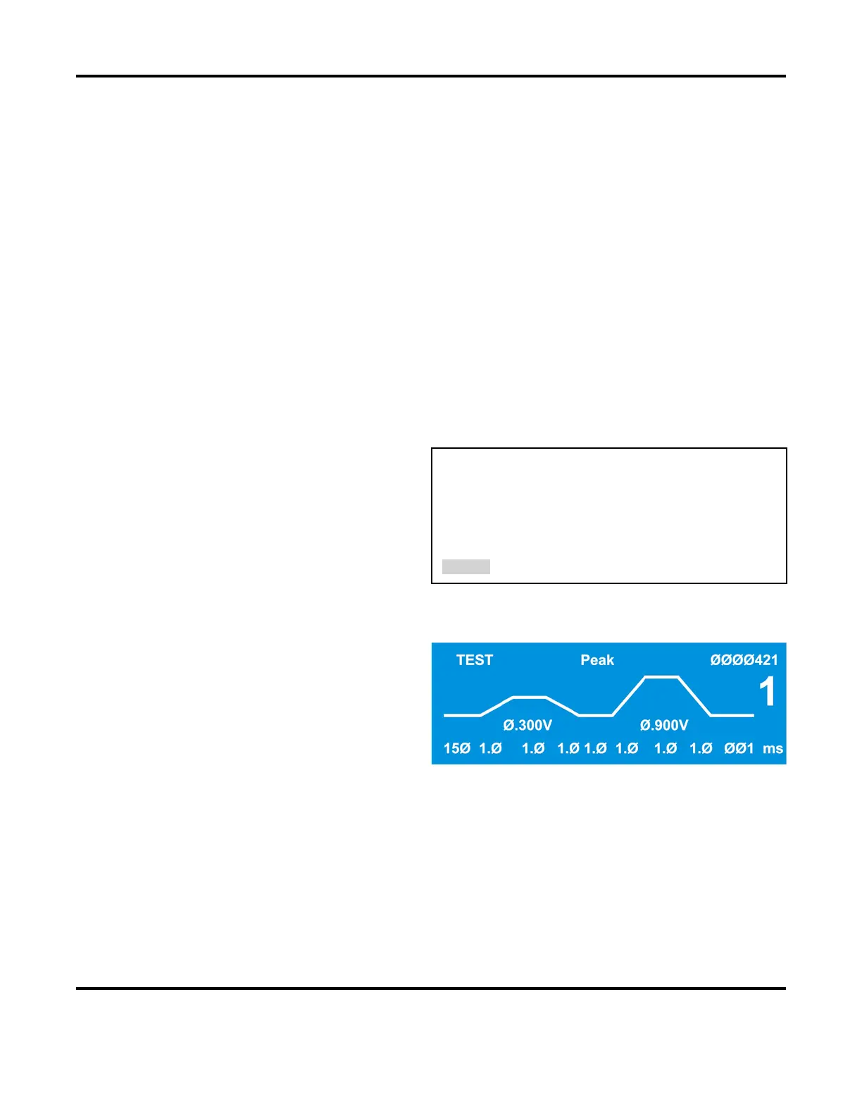
Test State
Programming a schedule for a voltage feedback
welding mode
, or changing the voltage or time
settings while in the voltage feedback welding
mode, puts the
Power Supply in the TEST state.
After making one weld, the
Power Supply
internally optimizes the feedback control loop to
produce the fastest rise time, minimum overshoot
weld pulse. The
TEST state is automatically
replaced by the run state for subsequent welds.